5G Beam Management Explained | DL Beamforming, SSB, CSI-RS, Codebook Types

Introduction
Downlink beam management is one of the most important parts of 5G Massive MIMO. It is the process used by the network to identify, refine, and maintain the best beam direction for each UE, starting from initial access and continuing during connected mode.
Unlike 4G, where beamforming was mainly tied to traffic channels, 5G extends beamforming to common, control, and traffic-related signals. This makes beam management much more important from both coverage and capacity perspectives.
This article focuses mainly on digital beamforming in mid-band 5G NR. It explains the beamforming life cycle, the roles of SSB and CSI-RS, the difference between Eigen-based beamforming and Grid of Beams, and how Type I and Type II codebooks support traffic beam selection.
Content
This article will cover:
- What 5G DL beam management is
- What are the main functions and stages of beam management
- Detailed technical breakdown
- Key parameters and where to find them
- Practical example walkthrough
- Summary key takeaways
(1) What 5G DL beam management is
5G DL beam management is the process of identifying and maintaining the best downlink beam for the UE. In practice, it starts in idle mode with SSB beam sweeping, then moves to beam pairing, followed by CSI-RS-based refinement, and finally traffic beam allocation for channels such as PDSCH.
At a high level, beam management answers three key questions:
- Which beam should the UE use first to access the cell?
- Which finer beam should be used after the UE enters connected mode?
- Which traffic beam should the gNB use to maximize link quality and throughput?
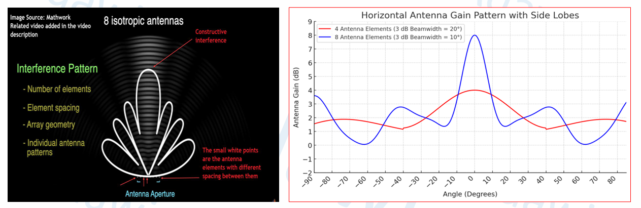
Massive MIMO makes this process more powerful than traditional MIMO because it uses more antenna elements. More elements create sharper and more directive beams, which improves antenna gain, reduces interference, and supports better MU-MIMO performance.
Another key advantage is 2D beamforming. In 5G Massive MIMO, the beam can be controlled in both the azimuth and elevation domains. This is especially useful in dense urban areas and high-rise environments.
To build the beam correctly, the transmitter needs channel-related information. In practice, this can come from:
- SRS in uplink, mainly for reciprocity-based beamforming in TDD
- CSI-RS feedback, where the UE measures downlink signals and reports CSI back to the network

(2) What are the main functions and stages of beam management?
The beamforming life cycle in 5G can be summarized as follows:
- Initial beam acquisition in idle mode
- Beam pairing during access and connection setup
- Beam refinement in connected mode
- Dynamic traffic beam allocation
- Beam mobility management
- Beam failure detection and recovery
The UE first finds the best SSB beam, then the network learns this beam through the PRACH association, then the beam is refined using CSI-RS, and later the traffic beam is allocated for actual user data transmission.
The goal is not only to find a beam once. The real objective is to keep the best beam over time while the UE moves, the channel changes, or the traffic conditions vary.

Which 5G channels and signals can be beamformed?
5G supports beamforming across more channels and signals than 4G.
A simple classification is:
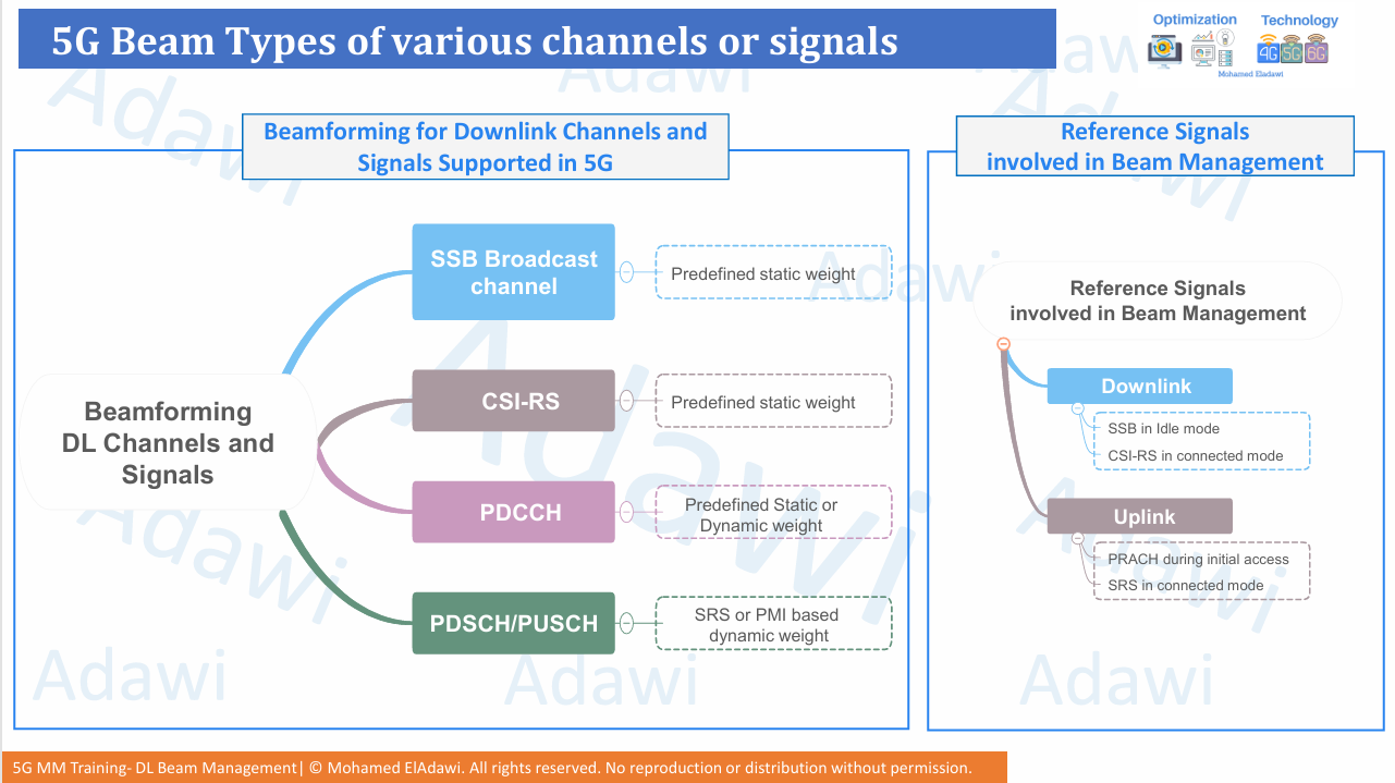
- SSB -> common beam, usually with predefined static weight
- CSI-RS -> connected-mode measurement beam, usually predefined for measurement purposes
- PDCCH -> control beam, static or dynamic depending on implementation
- PDSCH/PUSCH -> traffic beams, usually dynamic and based on CSI or SRS
The main reference signals involved in beam management are:
- Downlink
- SSB in idle mode
- CSI-RS in connected mode
- Uplink
- PRACH during initial access
- SRS in connected mode
(3) Detailed technical breakdown
3.1 SSB-based initial beam acquisition: Procedure 1
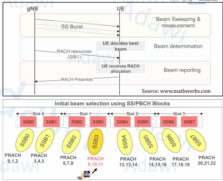
The first beam-management step happens in RRC Idle. The gNB transmits an SS Burst using different SSB beam directions, and the UE measures them to find the best one.
At the beginning, the UE does not know which beam is the best. It scans the transmitted SSBs, compares their radio conditions, and selects the beam with the best result, typically based on RSRP.
After decoding the SSB, the UE reads SIB1. From SIB1, it learns the RACH resources and the association between the selected SSB and the corresponding PRACH opportunities.
The UE then sends a PRACH preamble. Since the gNB already knows which PRACH resources are associated with which SSB, it can infer which SSB beam the UE selected. This is how the network identifies the initial beam pair.
In simple terms:
- The UE finds the best downlink SSB beam
- The UE sends PRACH using the associated resources
- The gNB infers the selected beam
- Initial DL/UL beam pairing is established
The standard maximum number of SSBs can be summarized as follows:
- FR1 up to 3 GHz -> up to 4 SSBs
- FR1 from 3 to 6 GHz -> up to 8 SSBs
- FR2 -> up to 64 SSBs
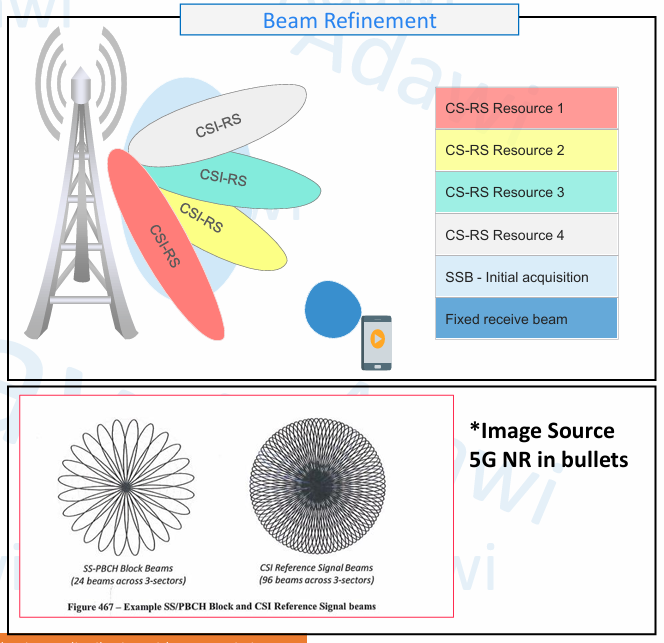
3.2 CSI-RS-based beam refinement: Procedure 2
After the initial beam is established, the next step is to move to a finer beam that is more suitable for connected-mode unicast transmission.
This is where CSI-RS-based beam refinement is used.
The concept is straightforward:
- SSB provides the initial beam
- CSI-RS provides a finer beam decision
Each SSB beam can be refined into multiple narrower CSI-RS beams. A common theoretical illustration is 4 CSI-RS beams per SSB, which means that 8 SSB beams could become 32 CSI-RS beams across the cell.
The UE measures these CSI-RS resources and selects the best one based on radio quality, especially RSRP. This leads to a more accurate beam decision, with better link budget and lower interference.
Narrower CSI-RS beams give the UE a better view of the downlink channel. This later helps the gNB form a better traffic beam for PDSCH.
In practice, the exact mapping between SSB beams and CSI-RS beams may vary depending on vendor implementation and deployment strategy.
3.3 Beamforming types Eigen-based vs Grid of Beams
5G beamforming can be grouped into two high-level categories:
- Eigen-Based Beamforming (EBB)
- Grid of Beams (GoB)
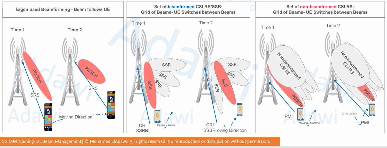
Eigen-Based Beamforming
In Eigen-based beamforming, the beam follows the UE more dynamically. The gNB uses SRS-based uplink measurements and channel reciprocity to estimate the downlink channel, then updates the beamforming weights accordingly.
This approach is mainly suitable for TDD, because uplink and downlink use the same frequency and reciprocity can be exploited.
Key characteristics:
- Dynamic beam update
- Good beam tracking
- Strong dependence on SRS and reciprocity
- Higher baseband processing demand
Grid of Beams
Grid of Beams uses a predefined set of beam directions. Instead of continuously building a new beam pattern, the network switches between already available beams.
This can be implemented in two forms:
- Beamformed GoB
- Examples: SSB beams or beamformed CSI-RS beams
- The UE reports the best beam using SSBRI or CRI
- Non-beamformed GoB
- The CSI-RS is transmitted without narrow-beam precoding
- The UE reports the best PMI, which helps the gNB choose the best precoding matrix
3.4 Codebook-based traffic beams Type I vs Type II
Once the UE has measured CSI-RS and the channel is better understood, the network can allocate the traffic beam for PDSCH.
Two main traffic-beam approaches are commonly used:
- Reciprocity-based beamforming using SRS
- Codebook-based beamforming using CSI feedback
The downlink focus here is the codebook-based path.
What does codebook mean?
A codebook is a predefined set of precoding matrices. The UE measures CSI-RS, identifies the best candidate, and reports feedback so that the gNB can apply the most suitable beamforming weights.
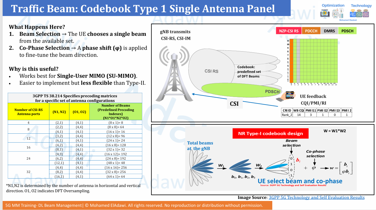
Type I codebook
Type I is the simpler approach and is mainly associated with SU-MIMO.
The process is:
- The gNB has a predefined beam set
- The UE selects one beam
- The UE also reports the co-phase information
- The gNB uses this feedback to form the final traffic beam
This is easier to implement, widely used, and effective for single-user transmission.
Type II codebook
Type II provides richer information and is more suitable for MU-MIMO.
Instead of selecting only one beam, the UE can report:
- A group of beams
- Their relative importance
- Amplitude scaling
- Co-phasing / linear combination information
This gives the gNB more spatial information and helps it separate users more efficiently in MU-MIMO scheduling.
The trade-off is clear:
- Better MU-MIMO support
- Better spatial separation
- Higher feedback overhead
- Stronger UE capability dependency

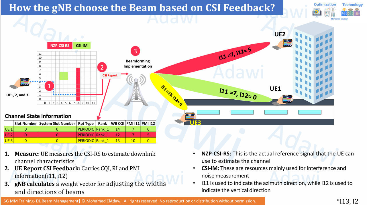
3.5 How the gNB chooses the beam from CSI feedback
The gNB chooses the beam by using the CSI feedback sent by the UE.
The flow is:
- The gNB transmits NZP-CSI-RS and CSI-IM
- The UE measures the downlink channel
- The UE reports CSI, which includes:
- CQI
- RI
- PMI
- The gNB calculates the beamforming weight vector
- The gNB sends the PDSCH using the chosen traffic beam
A practical interpretation of PMI is:
- i11 -> mainly related to the azimuth / horizontal direction
- i12 -> mainly related to the vertical / elevation direction
This means different UEs can report different PMI combinations depending on their location. For example:
- A UE on street level may need one horizontal beam and a low vertical beam index
- A UE in a high-rise building may need a different vertical beam index
- Another UE in a different street direction may need a different horizontal beam index
This is one of the clearest ways to understand how CSI feedback is translated into a traffic beam decision.
(4) Key parameters (and where to find them)
| Parameter | What it controls | Where it appears (SIB/RRC/DCI/log) | Practical note |
|---|---|---|---|
| Active SSB beams / SS burst positions | Defines how many SSB beam directions are active | SIB1 / cell configuration / logs | In mid-band, up to 8 SSBs is a common standard view, but deployment may use fewer |
| SSB-to-PRACH association | Maps the selected SSB to the PRACH opportunities | SIB1 / initial access configuration | This is the key link that lets the gNB infer the selected initial beam |
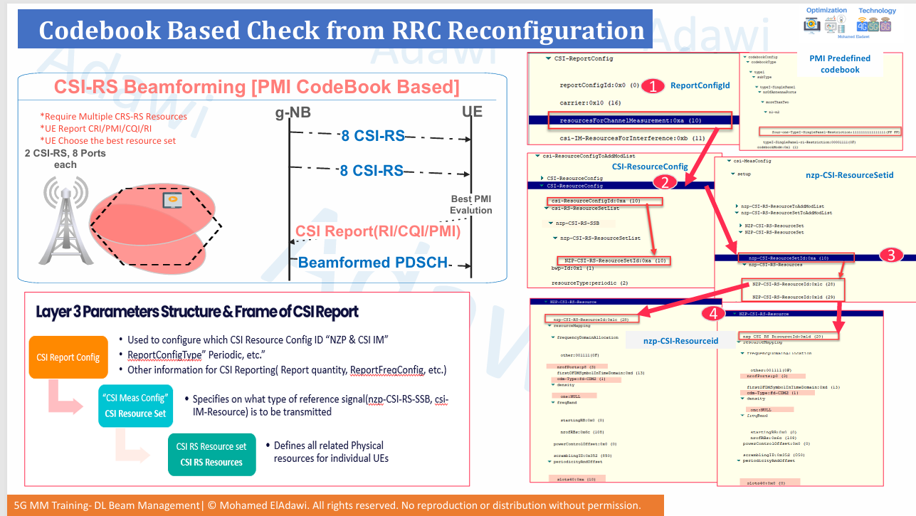
nzp-CSI-RS-ResourceSetId | Groups the CSI-RS resources used for channel measurement | RRCReconfiguration -> csi-MeasConfig | Start from the report config, then trace the referenced resource set |
nzp-CSI-RS-ResourceId | Identifies each individual CSI-RS resource inside the set | RRCReconfiguration -> csi-MeasConfig | Multiple resource IDs may mean multiple CSI-RS beams/resources |
nrofPorts | Number of CSI-RS antenna ports transmitted to the UE | CSI-RS resource configuration | More ports give more granularity, but also more overhead and stronger UE capability requirements |
| Codebook type | Selects the feedback/reporting method | RRCReconfiguration / UE capability | Type I is simpler and common for SU-MIMO; Type II is richer and better for MU-MIMO |
N1, N2 | Logical antenna dimensions in horizontal and vertical domains | Codebook configuration in RRC | Useful for understanding horizontal vs vertical beam granularity |
O1, O2 | Oversampling factors for the codebook grid | Codebook configuration in RRC | Higher oversampling means more predefined beam choices |
frequencyDomainAllocation | CSI-RS starting subcarrier pattern | CSI-RS resource mapping | Helps identify where the CSI-RS sits in frequency domain |
firstOFDMSymbolInTimeDomain | Starting OFDM symbol for CSI-RS | CSI-RS resource mapping | Useful when reading traces or visualizing resource placement |
density / cdm-Type | CSI-RS RE pattern and multiplexing method | CSI-RS resource mapping | These affect mapping, overhead, and how ports share REs |
periodicityAndOffset | Slot timing of periodic / semi-persistent CSI-RS | CSI-RS resource configuration | Critical when checking if the UE is measuring the expected CSI-RS occasions |
powerControlOffset / powerControlOffsetSS | Relative power between CSI-RS, PDSCH, and SS signals | CSI-RS resource configuration | Can influence CSI quality and access behavior |
PMI i11 / i12 | Beam direction information reported by the UE | CSI report / logs | i11 is commonly linked to azimuth and i12 to elevation in practical interpretation |
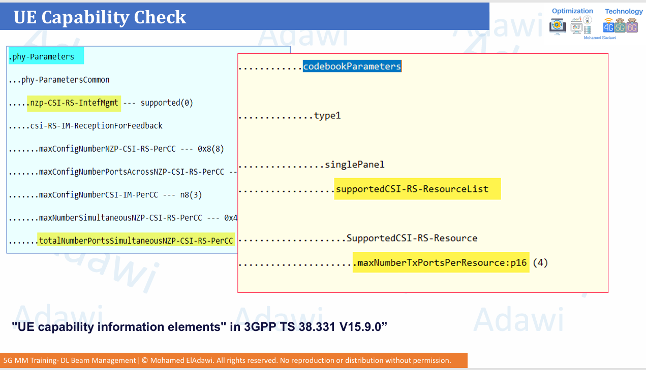
supportedCSI-RS-ResourceList / maxNumberTxPortsPerResource | UE capability for CSI-RS reception | UE Capability Information | Always check this before enabling higher CSI-RS port configurations |
(5) Practical example (walkthrough)
Consider a UE in idle mode in a mid-band 5G cell. The cell transmits several SSB beams. The UE measures all of them and finds that SSB beam 3 has the best radio condition.
The UE then reads SIB1, learns the associated PRACH resources, and sends the PRACH preamble using the occasions linked to that SSB. The gNB now understands which initial beam the UE selected, so the initial DL/UL beam pair is established.
After the UE enters connected mode, the gNB configures CSI-RS. Instead of keeping only the initial wide beam view, the network now uses a finer beam decision for user data.
The UE measures the configured NZP-CSI-RS resources and sends CSI feedback. In a simple Type I example, the UE reports the best beam direction through PMI, along with CQI and RI. The gNB then uses this to build the final PDSCH traffic beam.
Now consider two different deployment options:
- 32 CSI-RS ports with strong codebook granularity
- Better beam-selection granularity
- More overhead
- Stronger UE capability dependency
- 8 CSI-RS ports with beamformed CSI-RS resources
- Lower overhead
- Often better CSI-RS coverage
- Less traffic-beam granularity than the higher-port case
If the scenario contains many high-rise buildings, a configuration with more vertical control may be preferred. If the area is mostly flat, more horizontal beam granularity may provide better value.
This shows that beamforming design is not only a standards topic. It is also a deployment trade-off topic.

Summary (Key takeaways)
- 5G beam management starts with SSB-based initial acquisition, then moves to beam pairing, CSI-RS refinement, and finally traffic beam allocation.
- Massive MIMO improves beamforming because more antenna elements create sharper, higher-gain, more directive beams.
- 5G supports beamforming across common, control, and traffic-related signals, unlike 4G where the focus was mainly on traffic channels.
- Eigen-based beamforming is more dynamic and reciprocity-driven, while Grid of Beams uses predefined beam positions and switching/reporting.
- Type I codebook is simpler and common for SU-MIMO, while Type II codebook provides richer feedback and better MU-MIMO support at the cost of higher overhead.
- Real performance depends not only on the standard view, but also on vendor implementation, UE capability, and deployment choices.
References
- 3GPP TR 38.802, Section 6.1.6.1
- 3GPP TS 38.214
- 3GPP TS 38.331
- 5G NR in Bullets
- Massive MIMO for New Radio (Samsung white paper)
Video for the same
Related articles
- 5G HARQ Explained | Soft Combining, HARQ Processes, ACK/NACK Timing, Codebook Types, Spatial Bundling and 4G vs 5G Differences
- 5G SSB Explained | Cell Search, Frequency Positioning, Beam Sweeping and Overhead
- 5G Massive MIMO Fundamentals | Passive vs Active Antenna, MIMO Gains, and Antenna Specifications and Structure