5G Massive MIMO Explained: Key 5G Enabler, Physical Layer Processing, SU-MIMO, MU-MIMO, and Beamforming (Article)

Introduction
In the first Massive MIMO article, we focused on the antenna foundation: passive vs active antenna, antenna structure, antenna elements, and the basic MIMO concepts behind beamforming.
First Article: 5G Massive MIMO Fundamentals: Passive vs Active Antenna, MIMO Gains, and Antenna Specifications and Structure
This second part moves one step deeper. It explains why Massive MIMO is one of the key enablers of 5G, how it improves capacity and coverage, how the data stream is processed in the physical layer, and how the gNodeB decides which beam to use for SU-MIMO and MU-MIMO.
This topic matters a lot. because Massive MIMO performance is not only about having more antennas. It is also about how beams are formed, how layers are selected, how users are paired, and how uplink or downlink measurements guide the beamforming decision.
Content
This article will cover:
- What 5G Massive MIMO is?
- Why Massive MIMO is a key enabler for 5G
- How 5G Massive MIMO data streams are processed in the physical layer
- Massive MIMO features: SU-MIMO and MU-MIMO
- Beamforming logic: reciprocity based vs codebook based
- Key parameters and practical checks
- KPI and optimization impact
- Summary key takeaways
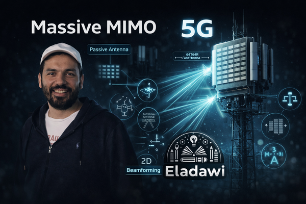
(1) What 5G Massive MIMO is?
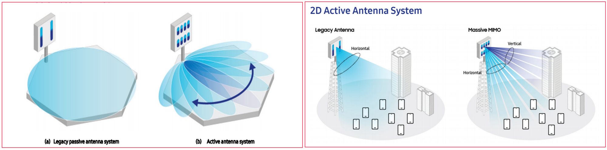
Massive MIMO is an active antenna system that uses a much larger number of antenna elements than legacy cellular antenna solutions.
In traditional passive antenna systems, the beam is relatively wide, fixed, and shaped to transmit energy in one general coverage direction. In Massive MIMO, the antenna can control the amplitude and phase of multiple RF chains and generate much narrower and higher-gain beams.
This gives the network much better spatial control. Instead of sending energy in a wide and less focused way, the gNodeB can steer energy toward the desired user more efficiently.
Another important difference is that Massive MIMO is not limited to only one plane. With more antenna elements and array structure, it can support both horizontal and vertical beam control. In simple words, it moves from a more limited beamforming model toward a 2D active antenna system.
(2) Why Massive MIMO is a key enabler for 5G
Massive MIMO is one of the key enablers of 5G because many 5G targets need both better capacity and better coverage at the same time.
This becomes even more important for enhanced mobile broadband, dense traffic areas, and higher-frequency deployments where propagation is more challenging. Without Massive MIMO, it becomes much harder to provide the expected user experience in real networks.
2.1 Capacity and spatial multiplexing gain
One of the biggest benefits of Massive MIMO is capacity improvement.
The gNodeB can use different beams and different spatial layers to serve one user or multiple users more efficiently. This means the network can improve spectral efficiency without simply depending on additional bandwidth.
In practical terms, Massive MIMO helps the network serve more users at the same time and make better use of the same time-frequency resources.
2.2 Coverage, sharp beams, and mmWave enablement
The second major benefit is coverage.
Because Massive MIMO uses many antenna elements, it can generate sharper and narrower beams. Narrower beams concentrate energy more efficiently toward the user, which improves useful signal strength and can also improve SINR by reducing unwanted leakage toward other directions.
This is especially important for high-frequency bands and mmWave. Those bands can provide high capacity, but they also suffer from higher propagation loss. Massive MIMO helps make those deployments more practical by improving beamforming gain and extending usable coverage.
Massive MIMO also supports 3D beamforming, or more accurately beamforming in both horizontal and vertical domains. This gives the network more freedom to shape coverage in a smarter way.
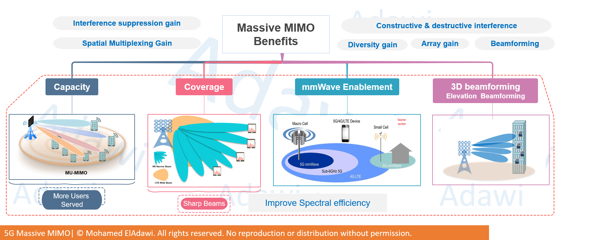
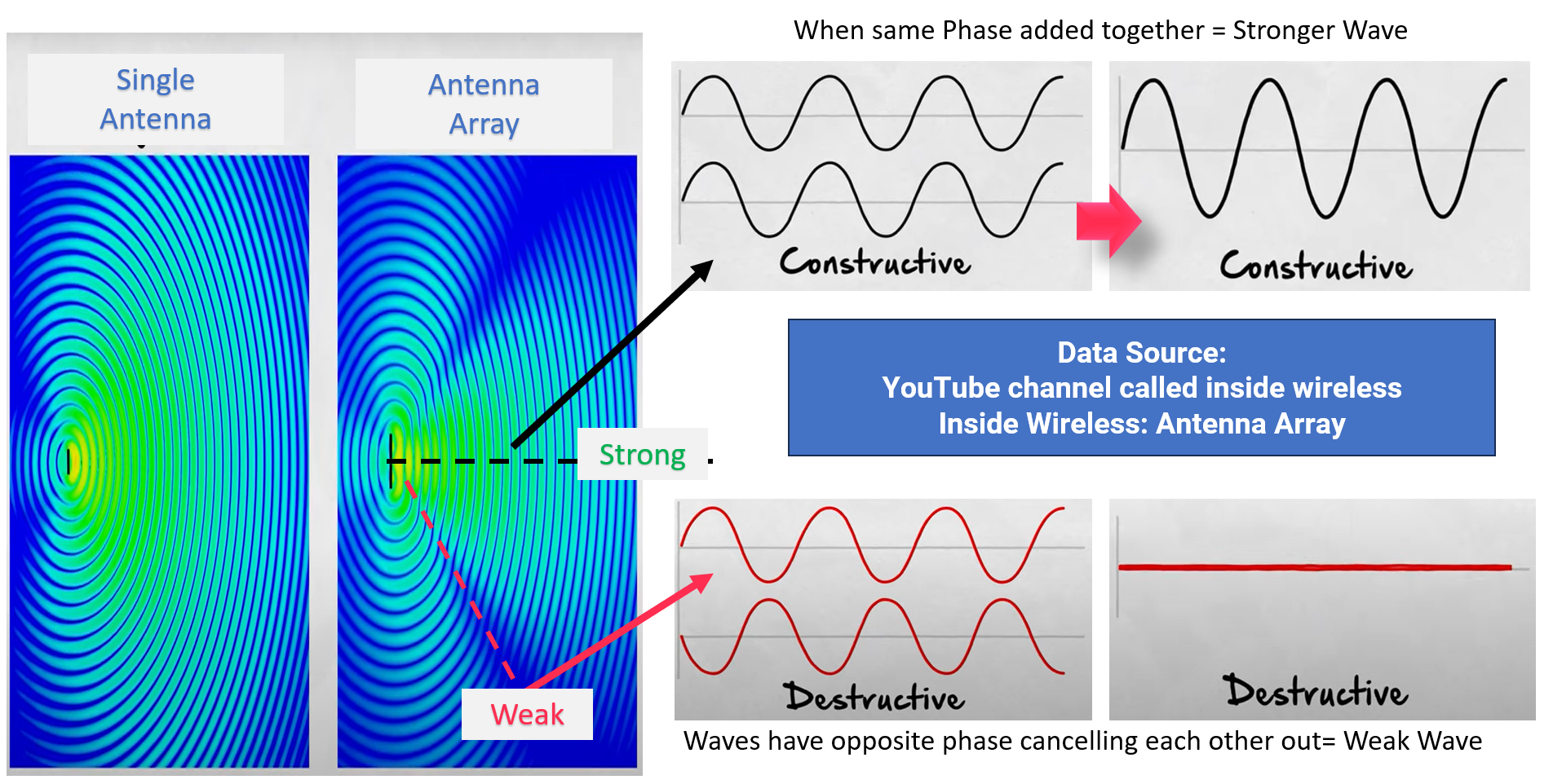
2.3 Array gain: constructive vs destructive interference
Another important concept behind Massive MIMO is array gain.
When signals from multiple antenna elements are added with the right phase relationship, they reinforce each other in the desired direction. This is constructive interference, and it helps create a stronger main beam.
At the same time, the antenna can make signals cancel each other in unwanted directions. This is destructive interference, and it helps reduce side radiation and interference.
So the goal is not only to make the wanted beam stronger. It is also to make the unwanted directions weaker. This is one of the reasons Massive MIMO gives better beam control than legacy antenna systems.
(3) How 5G data streams are processed in the physical layer
Before going deeper into SU-MIMO, MU-MIMO, and beam selection, it is useful to understand the high-level physical-layer flow.
This part matters because several important optimization levers sit inside this chain, especially modulation, layer mapping, precoding, beamforming, and resource mapping.
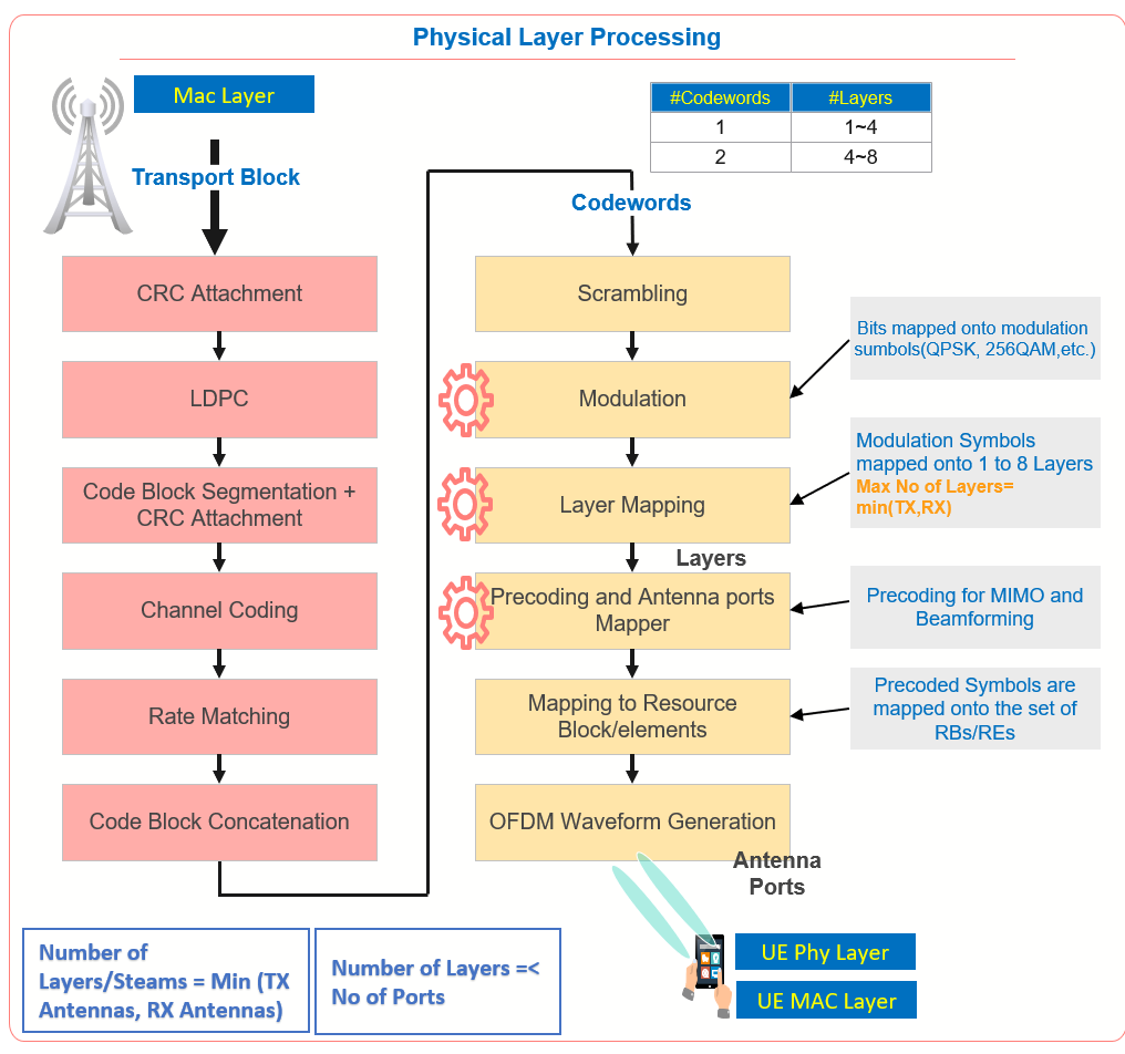
3.1 From transport block to codeword
The data starts as a transport block coming from MAC.
After that, CRC is attached for error detection. Then the data goes through LDPC-related processing, code block segmentation when needed, channel coding, and rate matching.
In simple words, this part prepares the data so it can be transmitted more reliably over the air.
A useful way to look at it is this:
- The transport block is the original MAC-layer data package.
- CRC helps detect whether decoding was successful or not.
- Coding and segmentation prepare the data for robust transmission.
- After that, the coded data becomes codeword-oriented processing in the PHY chain.
It`s important to highlight an important point about codewords and layers:
- 1 codeword can map to 1 to 4 layers
- 2 codewords can map to 4 to 8 layers
3.2 Modulation, layers, precoding, and antenna ports
After coding, the bits are scrambled and then mapped to modulation symbols such as QPSK or QAM.
Next comes layer mapping. This is where the modulation symbols are distributed over spatial layers.
A very important rule here is:
Number of layers or streams = minimum of TX antennas and RX antennas
So even if the gNodeB has many transmit chains, the final usable number of layers is still limited by what the UE can receive or transmit.
After layer mapping, the signal goes through precoding and antenna-port mapping. This is where MIMO and beamforming logic become very important.
Then the precoded symbols are mapped onto resource blocks and resource elements, and finally the OFDM waveform is generated for air-interface transmission.
A very important practical concept here is the difference between antenna ports and physical antennas:
- Antenna ports are logical or virtual signal paths used for transmission design and reference-signal behavior
- Physical antennas are the actual hardware radiating energy
This distinction becomes very important later when discussing CSI-RS, SRS, precoding, and beamforming.
(4) Massive MIMO features: SU-MIMO and MU-MIMO
At a high level, Massive MIMO gives two major transmission modes from a data-stream perspective:
- SU-MIMO for one user
- MU-MIMO for multiple users
Both aim to improve spectral efficiency, but they work differently.
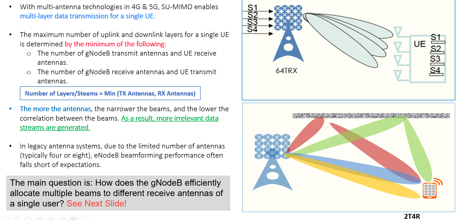
4.1 SU-MIMO
SU-MIMO means sending multiple spatial layers to one UE.
This is conceptually similar to the MIMO idea already known from 4G. The difference in Massive MIMO is that the much larger antenna array can create narrower beams and lower correlation between the spatial streams.
That gives better separation between layers and improves the chance of getting more useful parallel data transmission to the same user.
The maximum number of downlink or uplink layers for one UE is still limited by the minimum antenna capability between network side and UE side.
So even if the gNodeB has a large antenna array, the UE capability remains a key limiting factor.
In practical terms, Massive MIMO improves SU-MIMO because:
- the beams are narrower
- layer separation is better
- beamforming gain is higher
- interference between streams can be lower than in legacy systems
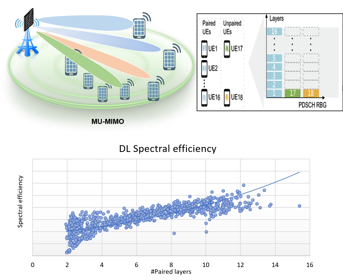
4.2 MU-MIMO
MU-MIMO takes the concept further by serving multiple UEs on the same time-frequency resources using different spatial beams or layers.
This is one of the most powerful capacity features in Massive MIMO.
Instead of giving one user the full spatial opportunity, the network can pair multiple users that are well separated in space and let them share the same PRBs while keeping them separated spatially.
This improves spectral efficiency and capacity without needing additional bandwidth.
The article highlights an important practical point: the key to MU-MIMO is UE pairing.
Good MU-MIMO performance depends heavily on:
- user spatial separation
- radio conditions
- beam orthogonality or low correlation
- antenna capability and product implementation
If users are too close in angle or too similar in channel condition, pairing becomes less efficient.
The article also highlights that in NR, MU-MIMO can apply beyond only user data and can be relevant to channels such as PDSCH, PDCCH, and PUSCH.
(5) Beamforming logic: reciprocity based vs codebook based
One of the most important questions in Massive MIMO is this:
How does the gNodeB know which beam to send?
At a high level, the article presents two main approaches:
- reciprocity based beamforming
- codebook based beamforming
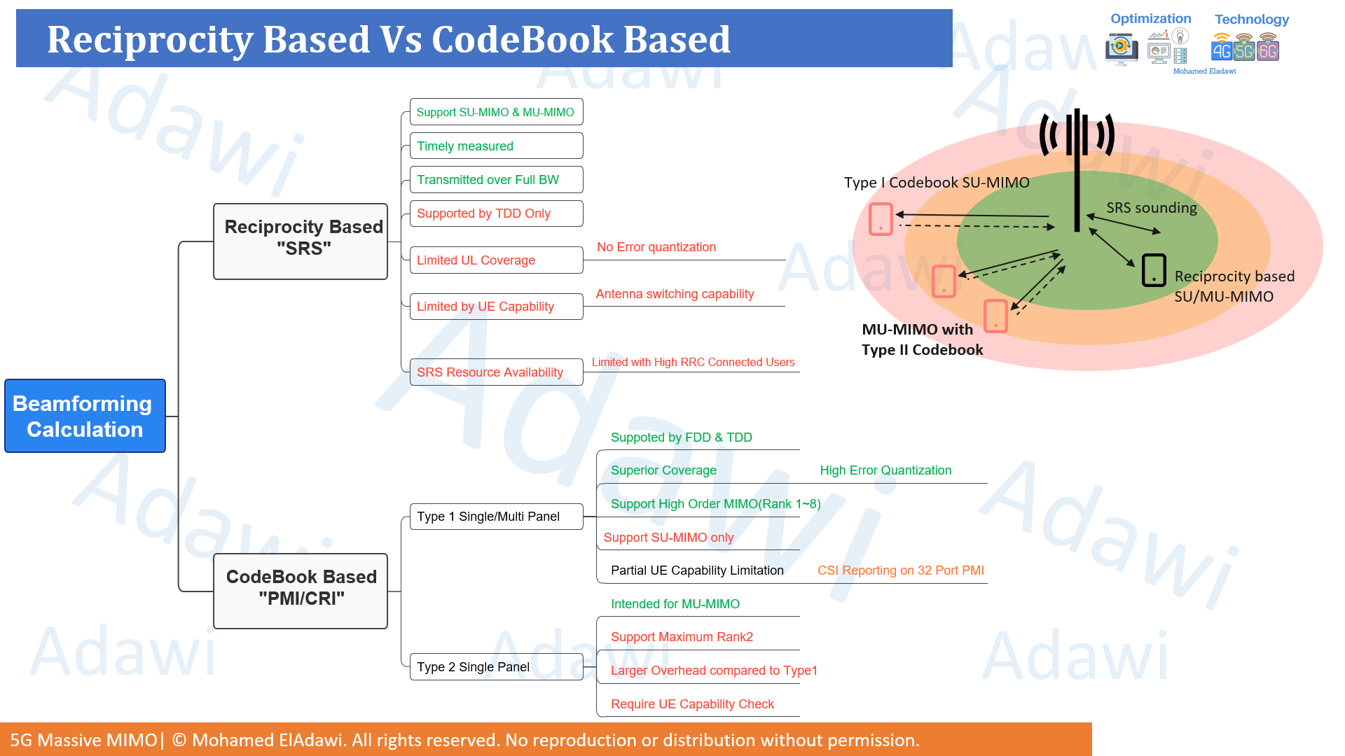
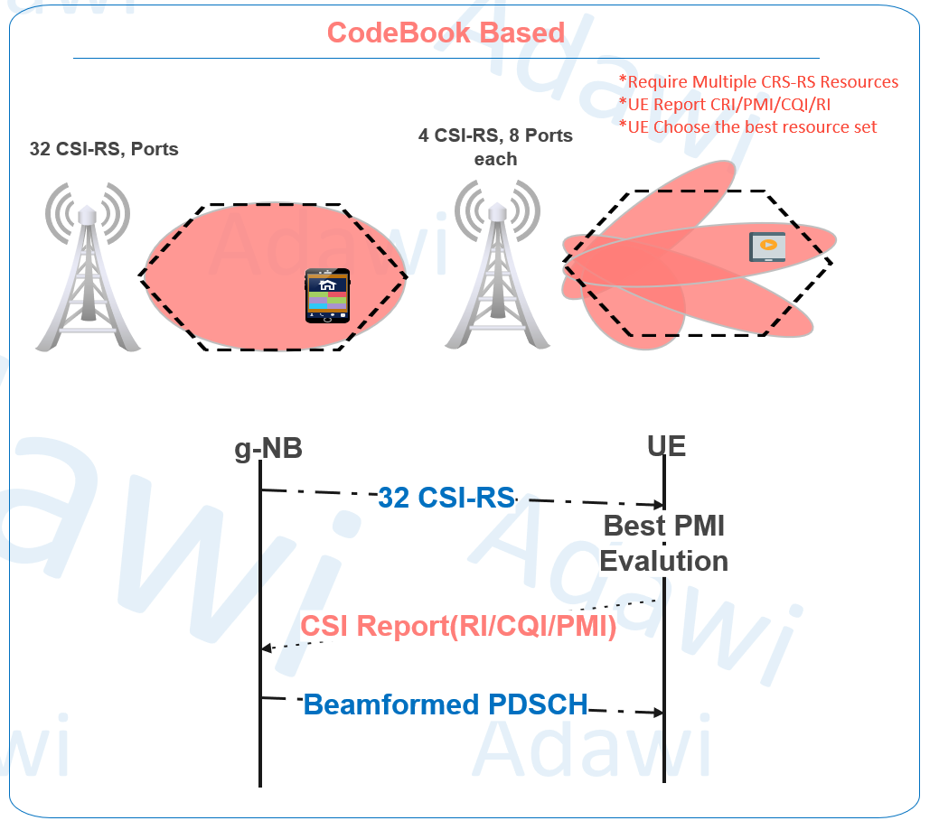
5.1 Reciprocity based beamforming using SRS
Reciprocity-based beamforming depends on uplink SRS.
The idea is that in TDD, uplink and downlink use the same frequency, but in different time slots. Because of that, the network can estimate the channel from uplink SRS and use it for downlink beamforming decisions.
This gives a fast and direct way for the gNodeB to calculate beamforming weights.
Main advantages:
- mainly suited for TDD
- timely measurement because the gNodeB directly measures the uplink signal
- sounding can be done over the full bandwidth
- no PMI quantization is needed
- useful for both SU-MIMO and MU-MIMO beam decisions
Main limitations:
- uplink coverage can limit accuracy, especially for edge users
- UE antenna switching capability matters
- SRS resource availability can become a limitation when many users are connected
So reciprocity-based beamforming can be very strong, especially for center users with good uplink quality, but it becomes more sensitive when uplink quality is weak.
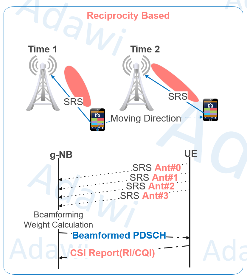
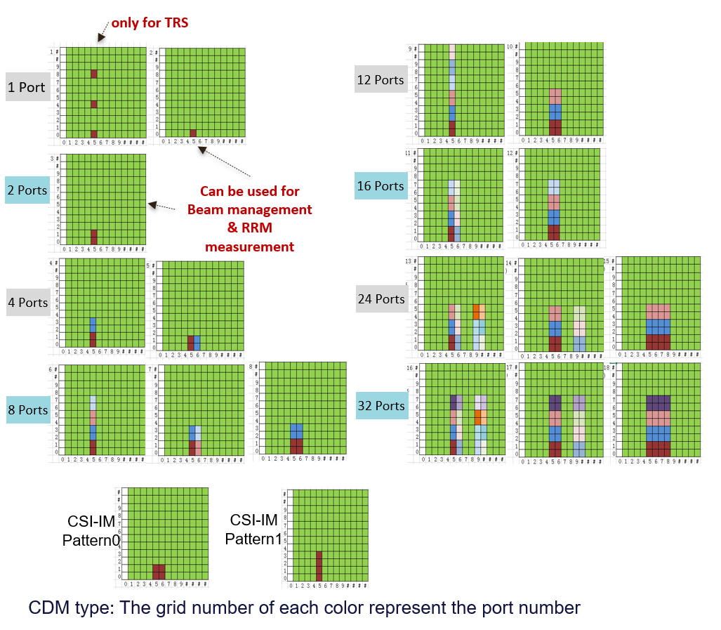
5.2 Codebook based beamforming using CSI-RS
Codebook-based beamforming works differently.
Here, the gNodeB transmits CSI-RS in downlink, and the UE evaluates what beam or precoding choice fits best. Then the UE reports feedback such as PMI, RI, and CQI.
In simple words, the UE helps the network decide which beam is better.
Main advantages:
- works in both FDD and TDD
- usually gives better practical robustness for edge users compared with pure SRS-based estimation
- the feedback path benefits from normal uplink channel protection mechanisms
- useful when reciprocity-based operation is not practical or not preferred
At a high level, there are two codebook families:
- Type 1, mainly presented as the stronger SU-MIMO-oriented option
- Type 2, mainly presented as the MU-MIMO-oriented option
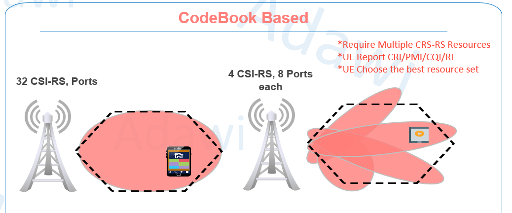
5.3 32-port CSI-RS vs 4 CSI-RS resources with 8 ports each
A practical comparison between a 32-port CSI-RS view and a split-resource view such as 4 CSI-RS resources with 8 ports each.
With 32 CSI-RS ports, the UE gets finer spatial granularity when evaluating the channel. That can help provide more accurate feedback for beam selection.
With multiple CSI-RS resources, the UE may first identify the best CSI-RS resource and then report feedback accordingly. In this case, CRI becomes relevant in addition to PMI, RI, and CQI.
So at a high level:
- more CSI-RS spatial granularity can improve beam selection quality
- split-resource approaches may be used to fit UE capability or configuration constraints
- there is a trade-off between granularity, overhead, and UE support
(6) Key parameters and practical checks
| Parameter / concept | Meaning | Where it appears | Practical note |
|---|---|---|---|
| Transport block | MAC-layer data entering PHY processing | MAC to PHY processing flow | One scheduling event may carry one or two transport blocks |
| Codeword | Encoded output used before modulation and layer mapping | PHY processing chain | 1 codeword can map to 1 to 4 layers, while 2 codewords can map to 4 to 8 layers |
| Layer / rank | Number of parallel spatial streams | MIMO configuration and CSI feedback logic | Final usable layers are limited by both network side and UE side |
| Antenna port | Logical transmission path used for precoding and signal mapping | PHY design, CSI-RS, PDSCH mapping | Antenna port is not the same as physical antenna |
| Physical antenna | Actual radiating hardware | Antenna hardware and AAU design | Massive MIMO benefits come from using many antenna elements and RF chains efficiently |
| SRS | Uplink sounding reference signal for channel estimation | Uplink reference signal configuration | Very useful for reciprocity-based beamforming, especially in TDD |
| CSI-RS | Downlink reference signal used for channel-state evaluation | CSI measurement and reporting configuration | Supports codebook-based beam decisions |
| PMI | Precoding matrix indication | UE CSI feedback | Tells the gNodeB which beam or precoding choice is preferred |
| RI | Rank indication | UE CSI feedback | Helps decide how many layers are suitable |
| CQI | Channel quality indication | UE CSI feedback | Strongly affects MCS and link adaptation |
| CRI | CSI-RS resource indicator | UE CSI feedback when multiple CSI-RS resources are configured | Helps identify which configured CSI-RS resource is preferred |
| Antenna switching capability | UE ability related to sounding across antenna branches | UE capability discussion for SRS usage | Can limit how effectively reciprocity-based sounding is used |
| SRS resource availability | Number of SRS resources that can be configured | Network configuration dimensioning | Can become a bottleneck in cells with many connected users |
(8) KPI and optimization impact
Massive MIMO directly affects several key performance areas.
Throughput and spectral efficiency
SU-MIMO improves peak-user throughput by sending multiple layers to one UE.
MU-MIMO improves cell throughput and spectral efficiency by allowing multiple users to share the same time-frequency resources through spatial separation.
Coverage and SINR
Sharper beams increase useful signal concentration toward the user.
At the same time, better beam control can reduce leakage toward unwanted directions, which helps SINR and improves cell-edge behavior.
Capacity in dense traffic areas
Massive MIMO is especially valuable in cells with high traffic demand because it increases the amount of traffic the same spectrum can carry more efficiently.
Beamforming method selection
Reciprocity-based beamforming can give strong performance when uplink sounding is reliable.
Codebook-based beamforming can be more robust in situations where uplink sounding is limited, especially for edge users or when FDD support is needed.
Practical optimization view
From an optimization point of view, the most important questions are usually:
- Are we getting the expected number of layers?
- Are users being paired effectively for MU-MIMO?
- Is the beamforming method suitable for the user location and coverage condition?
- Is the limitation coming from UE capability, uplink sounding quality, CSI granularity, or hardware implementation?
Summary key takeaways
- Massive MIMO is much more than just adding more antennas. It is about using many antenna elements to create smarter, sharper, and more controlled beams.
- It is one of the key enablers of 5G because it improves capacity, spectral efficiency, coverage, and high-frequency deployment practicality.
- SU-MIMO serves one user with multiple layers, while MU-MIMO serves multiple users on the same time-frequency resources through spatial separation.
- The physical-layer chain matters because modulation, layer mapping, precoding, and antenna-port mapping directly affect MIMO performance.
- Beamforming decisions are mainly guided either by reciprocity-based sounding through SRS or by codebook-based feedback through CSI-RS.
- Reciprocity-based beamforming can be very strong in TDD with good uplink sounding, while codebook-based beamforming is often more robust for edge users and supports both FDD and TDD.
- In real optimization work, UE capability, layer utilization, SRS quality, CSI feedback quality, and MU-MIMO pairing efficiency are some of the most important things to verify.
References
- Samsung Technical Whitepaper: Massive MIMO for New Radio
- Inside Wireless: Antenna Array (YouTube channel)
- 5G NR in Bullets