5G NR DMRS Explained (Part 1): What It Is, Where It Sits, and the Parameters That Control It
DMRS is the reference signal that lets the receiver demodulate PDSCH and PUSCH. Here is what it does, how it is placed in time and frequency, and which 3GPP parameters decide its configuration.

Every time a 5G base station sends data on the PDSCH, or a phone sends data on the PUSCH, a small set of known symbols travels with it: the Demodulation Reference Signal (DMRS). Without it, the receiver would have no reliable way to undo what the radio channel did to the data. This article is the first of a three-part series on shared-channel DMRS. It covers the fundamentals: what DMRS is, why it is needed, where it sits in the time-frequency grid, and which 3GPP parameters control it.
What is DMRS?
DMRS is a known reference signal sent together with PDSCH or PUSCH. Because the receiver knows exactly what was transmitted, it can compare that with what it actually received and estimate the channel. That estimate is what makes accurate (coherent) demodulation of the data possible. DMRS is UE-specific, and it exists in both directions:
- Downlink: the gNB is the transmitter and the UE decodes.
- Uplink: the UE is the transmitter and the gNB decodes.
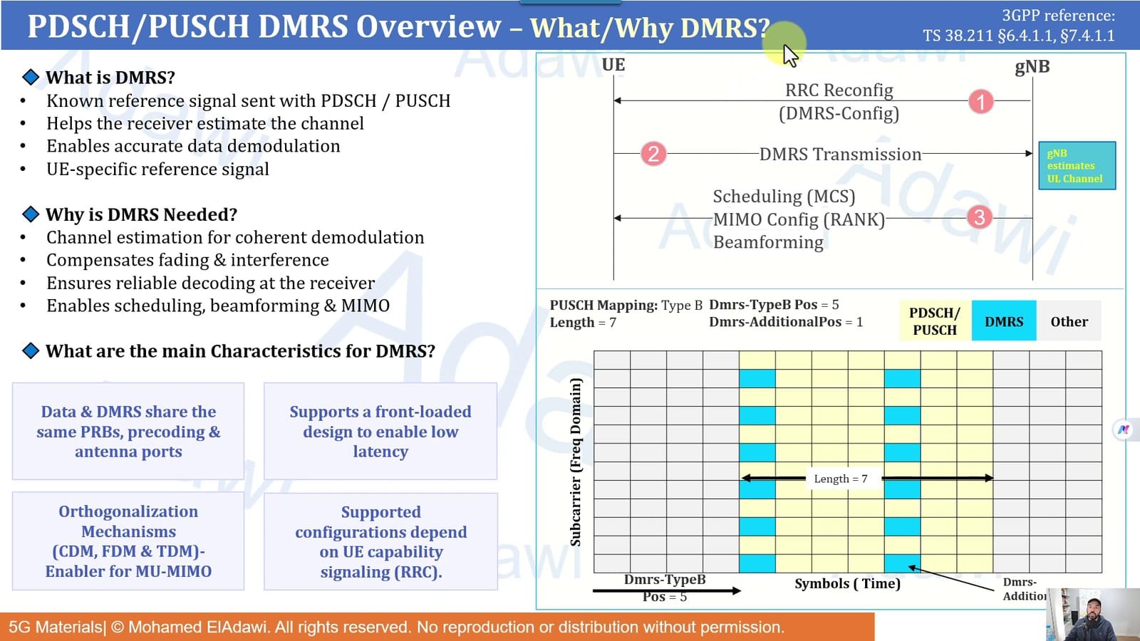
The flow is the same in both directions:
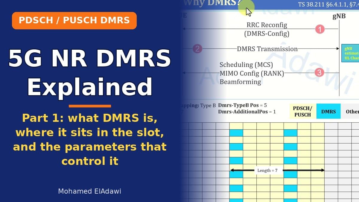
- Configuration. The gNB tells the UE how DMRS is configured (DMRS-Config) in RRC Reconfiguration. The UE now knows on which symbols and which subcarriers DMRS will be sent.
- Transmission. DMRS is transmitted along with the shared channel, for example on every second subcarrier in one or two symbols.
- Estimation and decisions. In the uplink, the gNB estimates the channel and decides MCS, rank and beamforming for the UE. In the downlink, the UE estimates the channel and reports feedback (rank, CQI, PMI), which the gNB then uses for scheduling, MIMO and beamforming decisions.
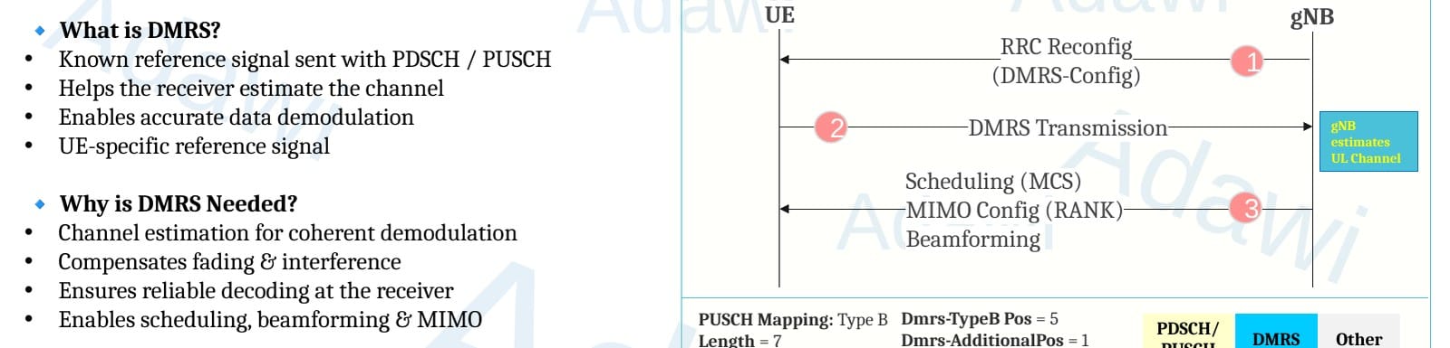
Why is DMRS needed?
- Channel estimation for coherent demodulation
- Compensating for fading and interference
- Reliable decoding at the receiver
- Feeding the scheduling, beamforming and MIMO decisions
The main characteristics of DMRS
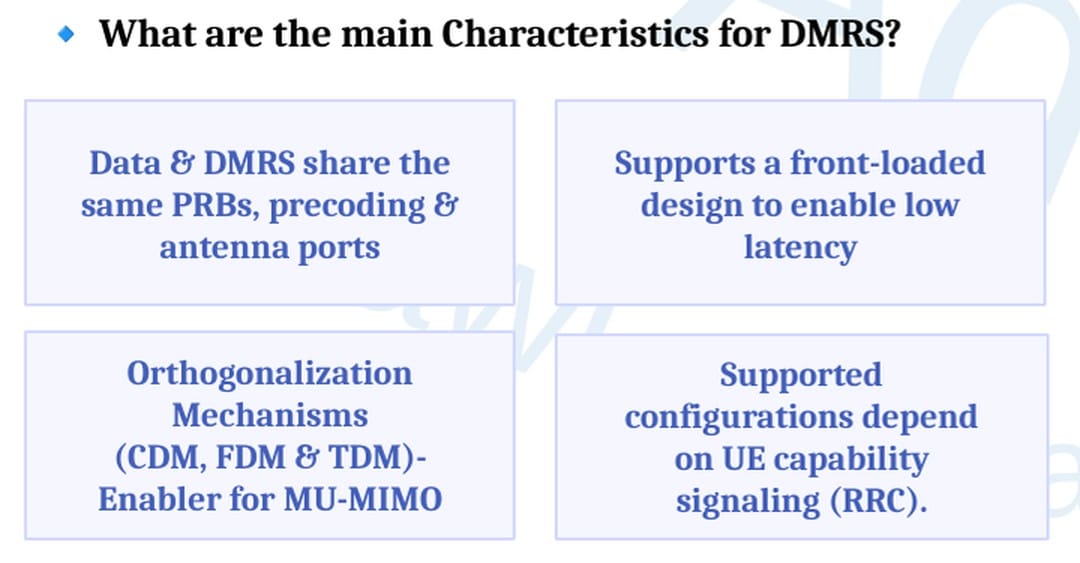
Data and DMRS share the same resources. This is the single most important rule. DMRS always sits inside the shared channel allocation. If the PDSCH is given 10 RBs, its DMRS spans the same 10 RBs, with the same precoding and the same antenna ports. That is exactly why the channel estimated from DMRS is valid for the data.
Front-loaded design for low latency. DMRS can be configured to come in the first symbol of the shared channel. The receiver can then start channel estimation and decoding early instead of waiting for later symbols.
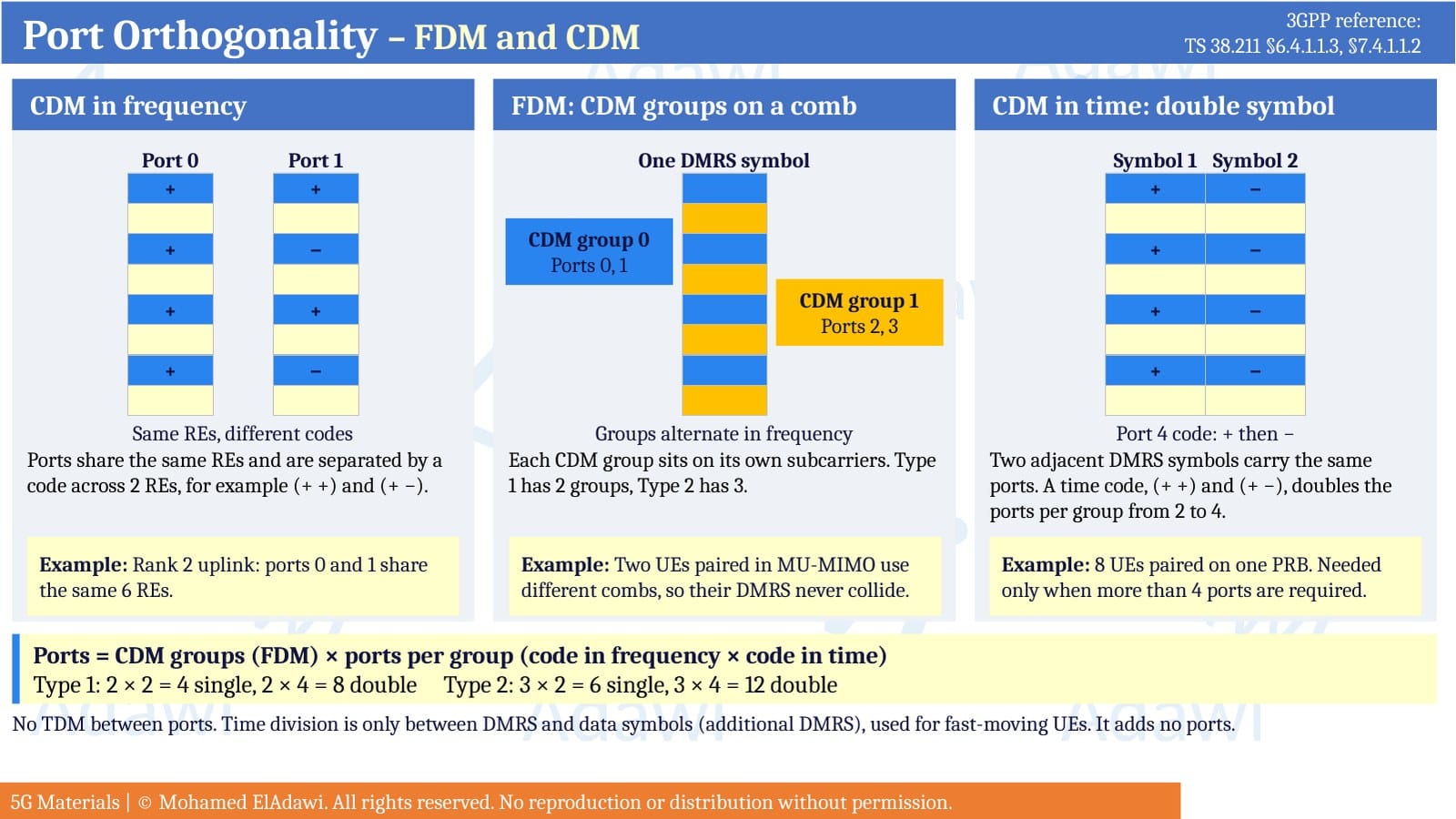
Orthogonality mechanisms (CDM, FDM and TDM). Different DMRS ports are separated by code, frequency and time. This is what enables multiple layers and MU-MIMO.
Configurations depend on UE capability. Not every UE supports every DMRS configuration. The UE reports what it supports, and the gNB can only configure those features.
Where DMRS sits in the frame
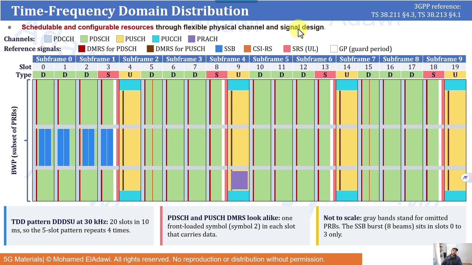
It helps to always picture where channels and reference signals live in the frame. In a TDD DDDSU pattern at 30 kHz SCS, every slot that carries PDSCH has its DMRS, every slot that carries PUSCH has its DMRS, and even the special slot carries DMRS for its downlink part. The exact positions in time and frequency change with configuration, but the concept is the same for every vendor.
Frequency domain: Configuration Type 1 vs Type 2
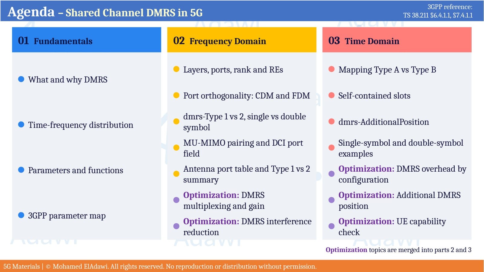
DMRS configuration has two halves: the frequency domain (which subcarriers carry DMRS) and the time domain (which symbols carry DMRS).
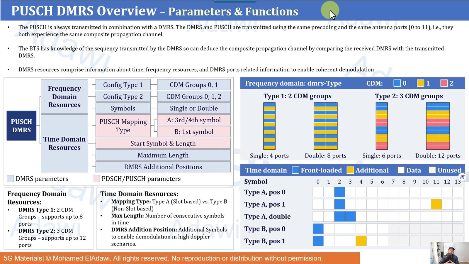
In the frequency domain, the key parameter is dmrs-Type:
| Type 1 | Type 2 | |
|---|---|---|
| Pattern | Every 2nd subcarrier | 2 adjacent subcarriers per CDM group |
| REs per RB per symbol (one CDM group) | 6 of 12 | 4 of 12 |
| CDM groups | 2 | 3 |
| Max ports | 4 (single symbol), 8 (double) | 6 (single symbol), 12 (double) |
| Strength | Denser pilots, better channel estimate | Lower overhead, more room for data and MU-MIMO |
Type 1 gives the receiver more DMRS to read, so it fits harder radio conditions. Type 2 frees resource elements for data and supports more orthogonal ports, which can raise peak throughput and MU-MIMO capacity where radio conditions are good. Some vendors switch dynamically between the two based on channel quality.
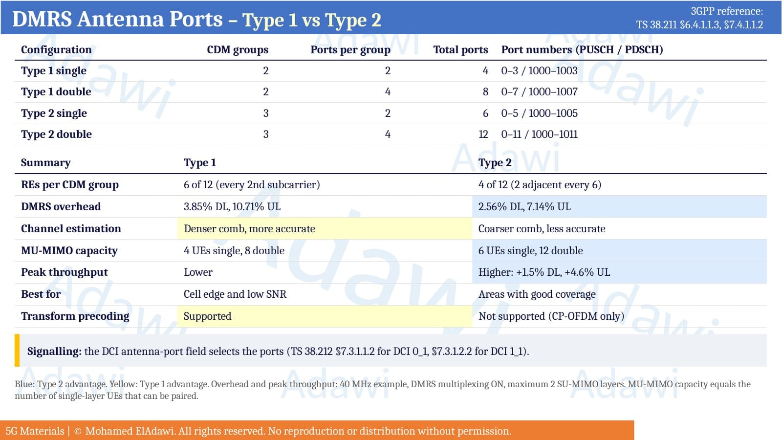
The number of DMRS symbols also matters. Single symbol keeps overhead low. Double symbol (two adjacent DMRS symbols) doubles the available ports and improves estimation, at the cost of more overhead.
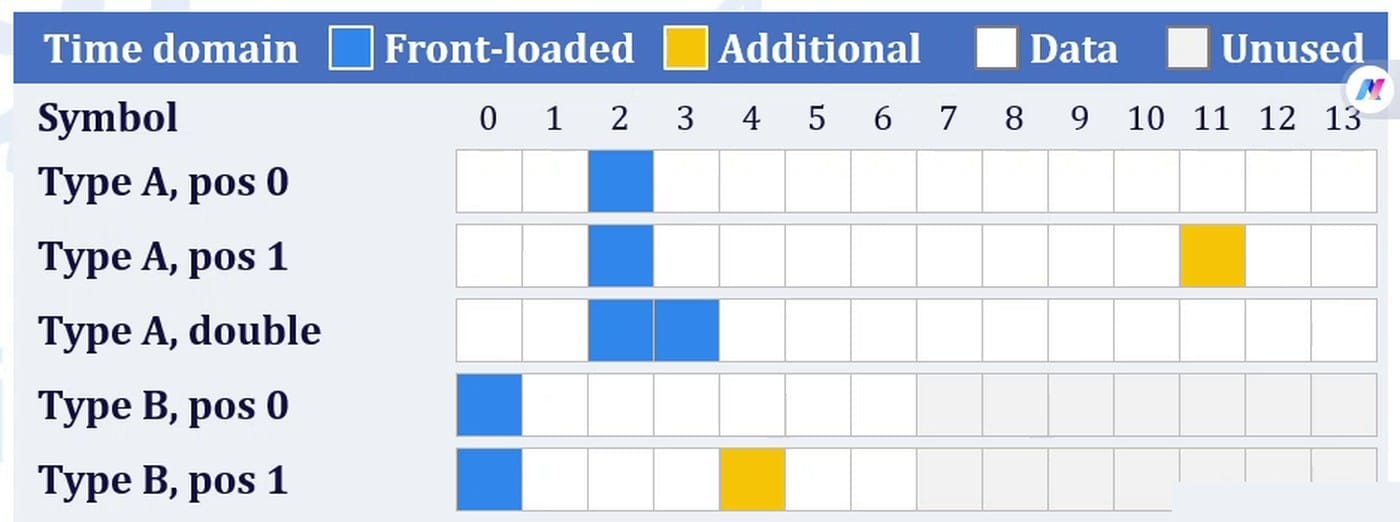
Time domain: where the first DMRS symbol goes
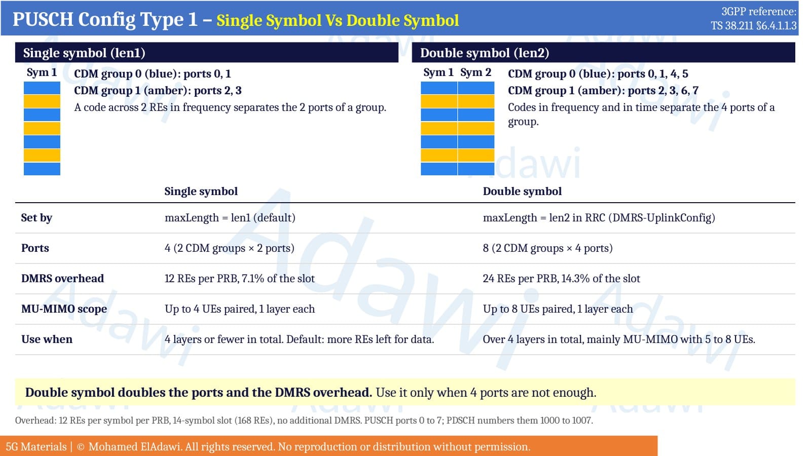
Time-domain placement is mostly controlled by parameters of the shared channel itself (PDSCH or PUSCH), not by the DMRS section, because DMRS always follows the shared channel.
- Mapping Type A (slot based): the first DMRS is in symbol 2 or 3 of the slot, as set by dmrs-TypeA-Position in the MIB. Because it does not follow the start of the allocation, it is not called front-loaded.
- Mapping Type B (non-slot based): the first DMRS is always in the first symbol of the allocated PDSCH or PUSCH. This is the front-loaded case.
- Start symbol and length (from startSymbolAndLength) tell the UE where the shared channel begins and how many symbols it uses. DMRS is placed inside that window.
- dmrs-AdditionalPosition adds extra DMRS symbols later in the allocation (pos0 to pos3). This helps in mobility and high-Doppler scenarios but adds overhead.
- maxLength selects single-symbol (len1) or double-symbol (len2) DMRS.
Where to find the parameters: RRC and MIB
The configuration reaches the UE in two places: the RRC Reconfiguration message (dmrs-Type, dmrs-AdditionalPosition, maxLength, scrambling IDs, under PDSCH-Config or PUSCH-Config) and the MIB (dmrs-TypeA-Position).
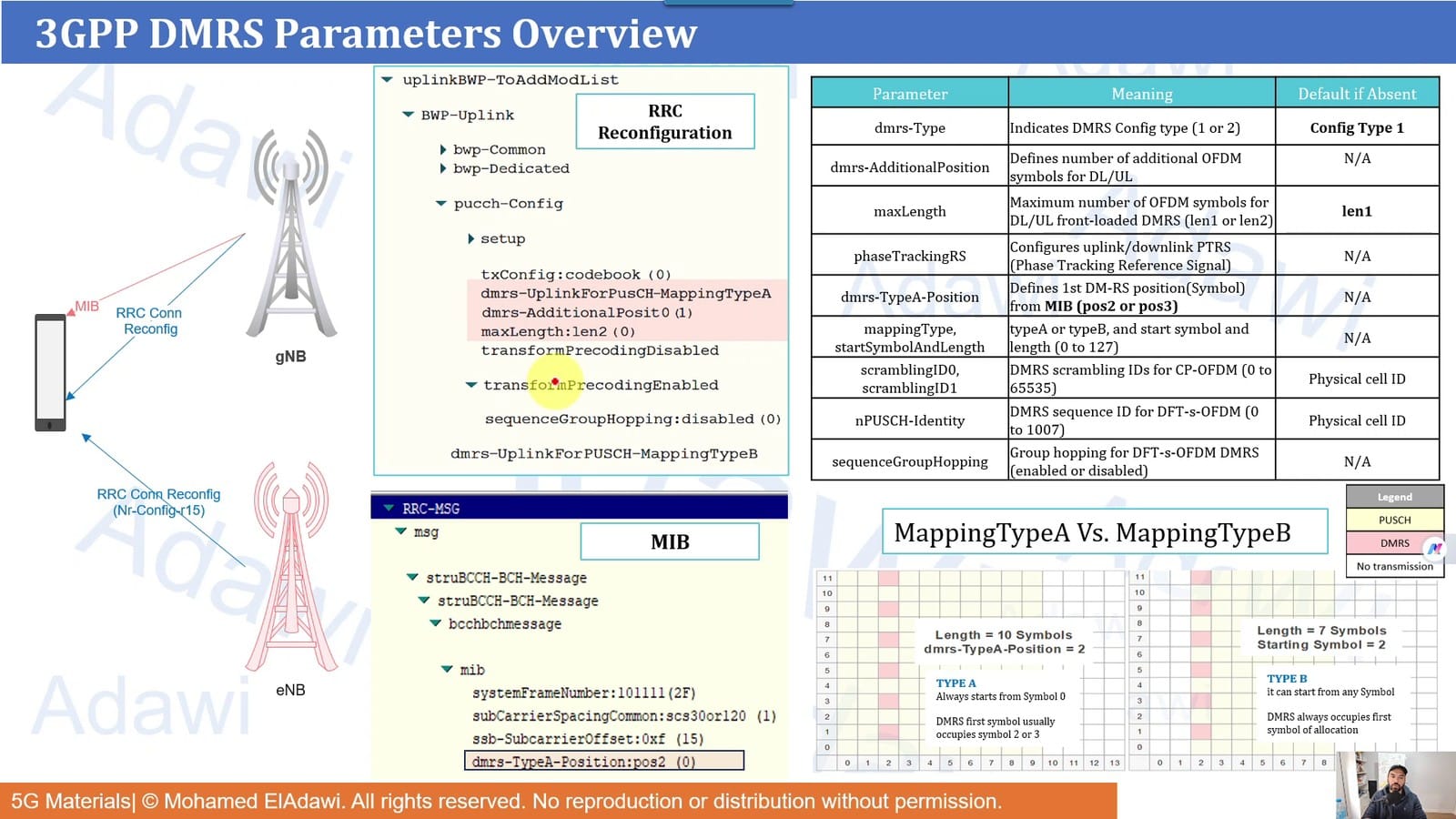
Two defaults are worth remembering when you read a trace:
- If dmrs-Type is absent from RRC, the UE uses Configuration Type 1. Type 2 must be configured explicitly.
- If maxLength is absent, it is len1 (single symbol).
What's next
Part 2 goes deep into the frequency domain: layers, ports and rank, CDM and FDM, Type 1 vs Type 2 port tables, MU-MIMO pairing and DMRS multiplexing. Part 3 covers the time domain in detail, with live-network examples and the optimization trade-offs of additional DMRS.
3GPP references: TS 38.211 §6.4.1.1 and §7.4.1.1, TS 38.214 §5.1.2.1 and §6.1.2.1, TS 38.331.