5G RAN Features/Parameters Part 2(Post)

This article simplifies the basic understanding of 4 features/parameters and explains how to verify features functionalities from the traces and field testing. The same content was already explained earlier in a YouTube video (shared below), but this post adds some additional information to be used a reference.
Before starting and moving into the feature/parameters part, let`s first recall our knowledge and have a high-level overview of DMRS for PDSCH, as this will ease our understanding of all related PDSCH DMRS-related parameters and features.
DMRS FOR PDSCH(Overview)
What are the function and main Characteristics of DMRS for PDSCH?
DMRS Function --> The UE uses DMRS to estimate the propagation channel experienced by the PDSCH.
The Main Characteristics of DMRS are summarized in the below points:
• PDSCH is always transmitted in combination with DMRS; this means that DMRS will be only available during PDSCH resource allocation, and both(PDSCH and DMRS) use the same antenna ports(1000 to 1011)
• DMRS for PDSCH supports a wide range of configurations “Flexible.” This configuration account for the requirements associated with both Single User and MU-MIMO
• In general, DMRS Configurations depend upon the following variables:
1- PDSCH DMRS Configuration Type 1 or Type 2
2- Single or Double Symbol
3- PDSCH Mapping Type A or B
4- PDSCH DMRS Additional Positions
5- DMRS Starting Symbol for Mapping Type A
6- PDSCH Duration
Now, Let`s have a high-level introduction about PDSCH DMRS Configuration type 1, and later on, I will cover all details regarding all DMRS configurations.
To simplify the meaning of the word Characteristic, it simply means how the Frequency and time domain resources will be allocated to all Users and how-to will be decoded by Users. Let`s go through and try to figure out the main function of DMRS Configuration types(Type1).
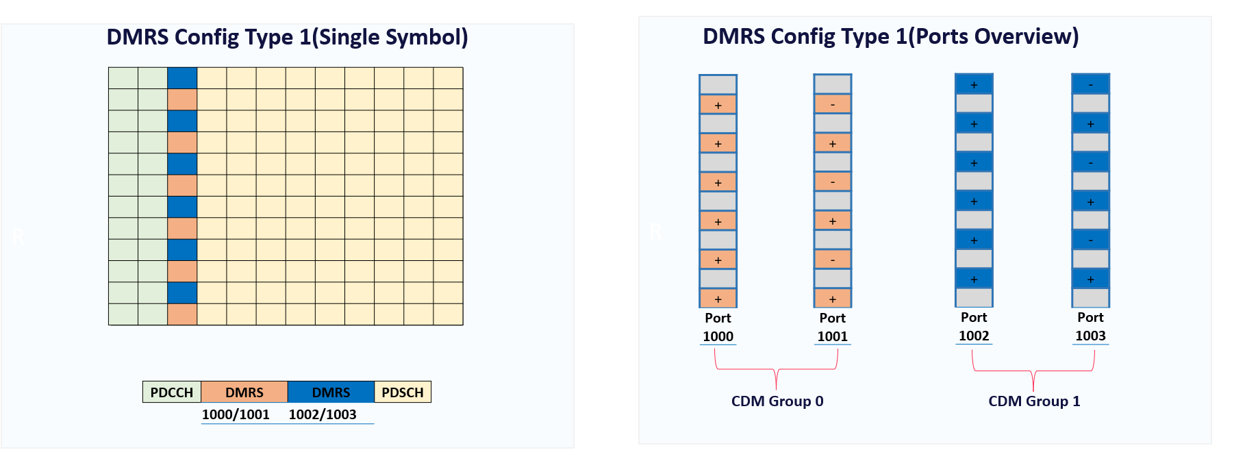
In general, DMRS for PDSCH supports two types of configuration which are 1 & 2. Configuration Types impact the frequency domain resource allocation, taking Configuration Type 1 as an example.
Configuration type 1 supports the following:
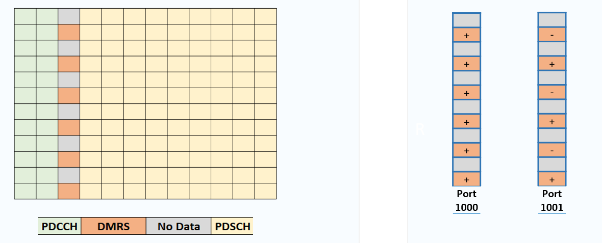
1) 4 antenna ports(1000 to 1003)
2) Two CDM Group. CDM means Code division multiplexing, which simply means that different users can the same resource location (for example, the same Resource element) by using different antenna ports and using different Codes.
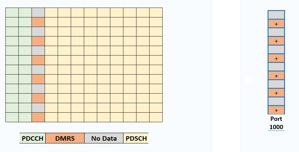
3) Configuration Type 1 allocates every second Resource element to the MDRS. This creates a transmission comb and allows frequency and code multiplexing for the DMRS Antenna ports
- For example, as shown in the below figure, Antenna port 1000/1001(Orange color) can be frequency multiplexed with antenna port 1002/1003(Blue color)
- Another example, as shown in the below figure, antenna ports sharing the same resource elements, such as 1000 and 1001, are differentiated using Orthogonal Cover Code(OCC) which allows Code Division Multiplexing.

FDM --> Frequency Division Multiplexing
CDM --> Code Division Multiplexing
Let`s try to simplify further regarding FDM & CDM.
Assume you have a Single User MIMO with Rank1; this user will require only one antenna port(Ex. Antenna Port 1000). which will occupy every second Resource element(Occupy 50% of the Resource elements within the Symbol).
Now Assume that the same users are now capable of Rank2; this means that this user will now require two antenna ports. In that case, This user will start using Port 1000 and 1001, which share the same resource elements but are differentiated using Orthogonal Cover Code(OCC) which allows Code Division Multiplexing. (Still Occupying 50% of the Resource elements within the Symbol)
Important Note, Code division Multiplexing is prioritized over frequency division multiplexing
Now Assume that the same users are now capable of Rank3/4; this means that this user will now require three/four antenna ports. In that case, This user will start using Port 1000 to 1003; in that case, in addition to CDM, which was previously explained, Now Antenna ports 1000 and 1001 can be frequency multiplexed with antenna ports 1002 and 1003.
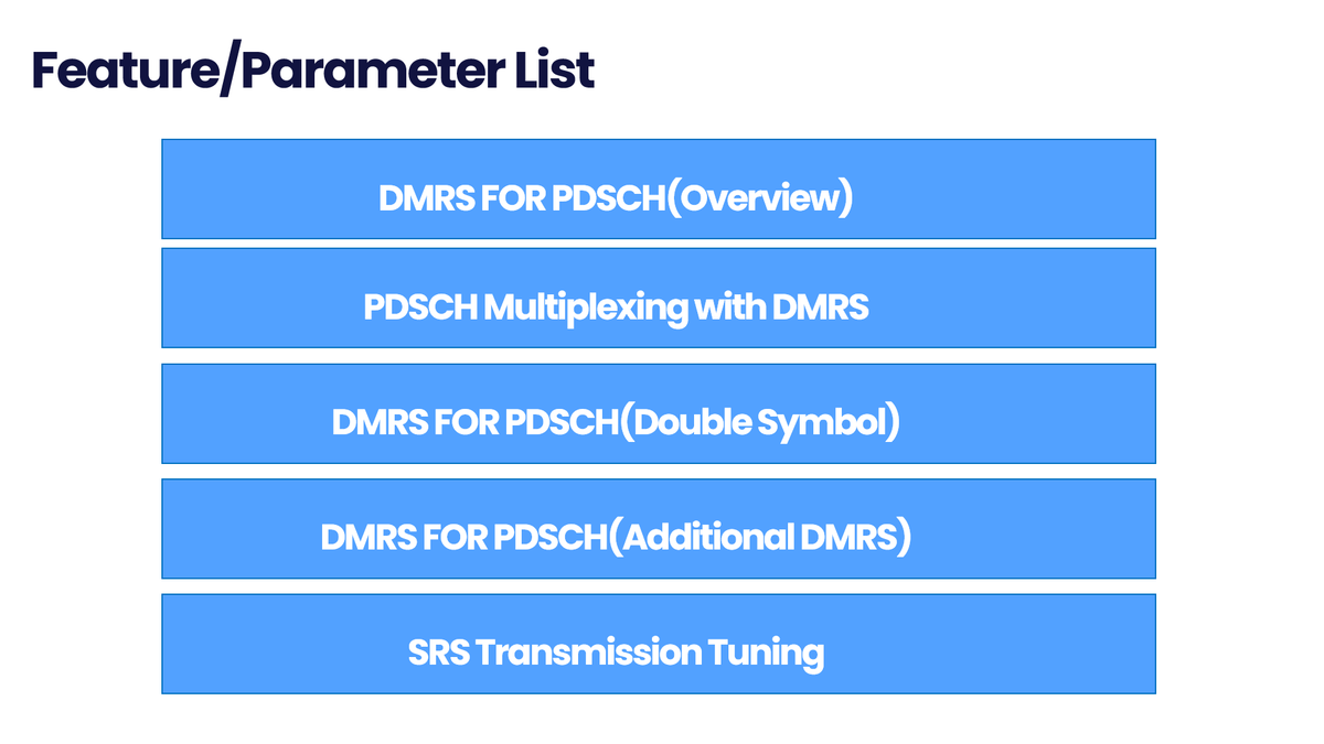
Now, Let`s cover the main feature/parameters.
Feature 1: PDSCH Multiplexing with DMRS
PDSCH Multiplexing with DMRS simply means allocating the free resources within the DMRS symbol to the DMRS to improve the DL User throughput
Assume A UE receiving 2 layers of data (Rank2) with Single User MIMO can be allocated antenna ports 1000 and 1001. CDM is prioritized over FDM.
This part of ports occupies only half of the Resource Elements within the DMRS Symbol; in this case, the resource elements can be used by the PDSCH.
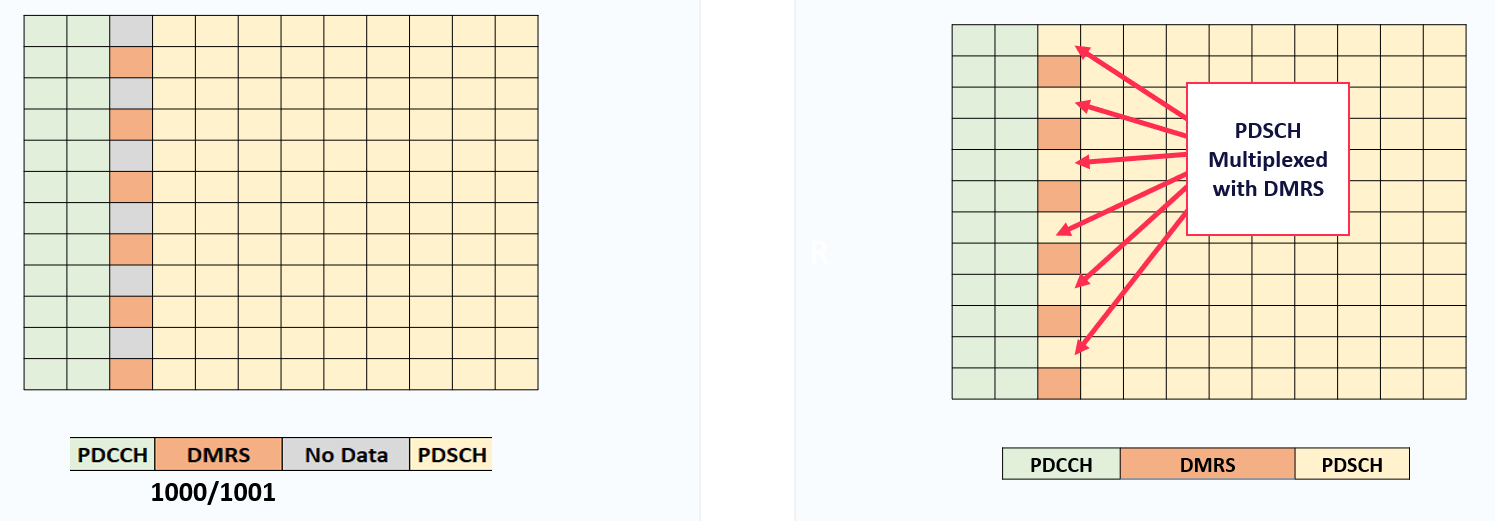
as explained in the overview part, FDM will not be allowed with PDSCH incase of R3/; for Example, A UE receiving 4 layers of data (rank 4) with Single User MIMO can be allocated antenna ports 1000 to o1003. These 4 antenna ports occupy the DMRS symbol, and there are no Resource Elements available for the PDSCH.
Summary:
Expected Gain: Increase in the maximum User throughput for users in good radio condition
Expected Drawbacks: DRMS power boosting is not allowed if the PDSCH is multiplexed with DMRS
PDSCH Multiplexing is not supported for Rank 3, Rank 4, and MU-MIMO Users, Because all 4 ports will be utilized as highlighted in the intro slide
Feature 2: DMRS FOR PDSCH(Double Symbol)
- A pair of symbols increases the code multiplexing capability of the DMRS. i.e., there are 4 antenna ports per CDM group rather than 2 antenna ports per CDM group.
- This increases the total number of antenna ports and so increases the scope for Multi-User MIMO
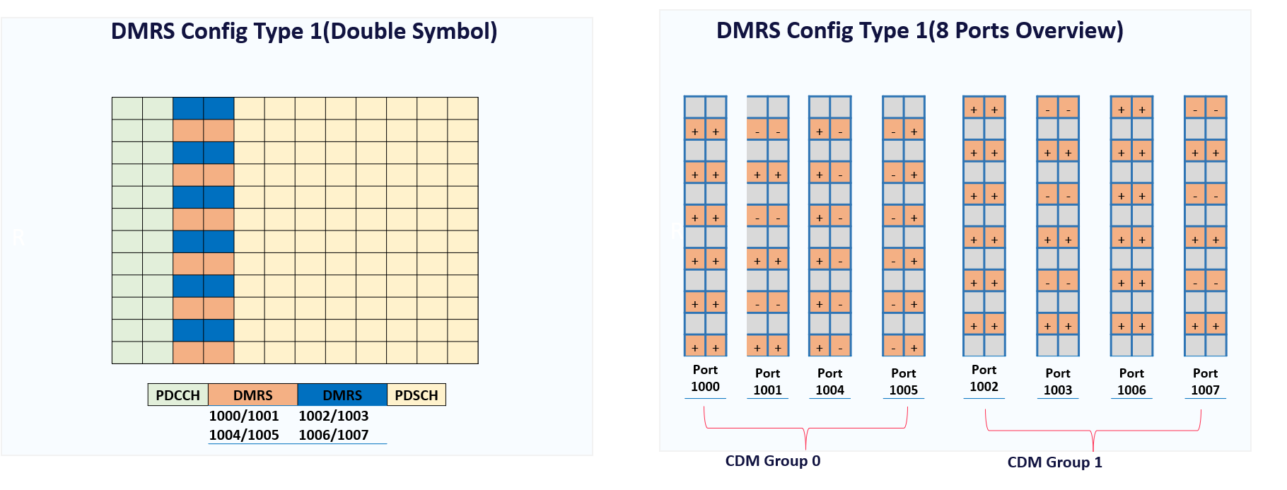
- The use of double Symbols DMRS can be restricted using the max length parameter. If this parameter is excluded from DMRS-DownlinkCOnfig, then only single symbol transmission is permitted.

Summary:
Expected Gain: Increase in the Scope of MU-MIMO. More Users can be paired, which can increase the Cell Capacity in the very high-traffic scenarios
Expected Drawbacks: Overhead increase will impact the maximum user speed
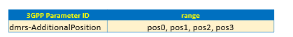
Feature 3: DMRS FOR PDSCH(Additional DMRS)
The additional DMRS Symbol is controlled by the following parameter
where pos0 = 0 additional symbols, pos1 = 1 additional symbol, pos2 = 2 additional symbols and pos3 = 3 additional symbols
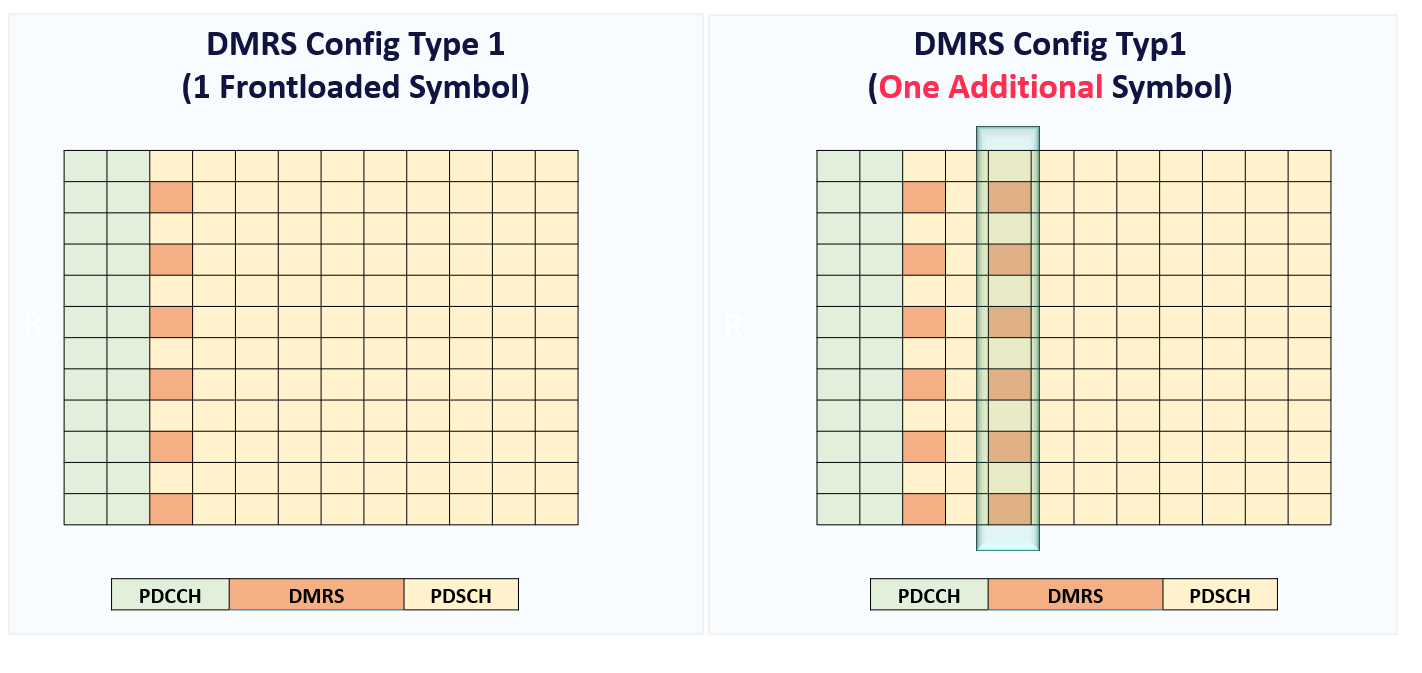
Using Additional DMRS symbols can help to improve the UE channel estimation performance.
If a PDSCH transmission includes 2 DMRS symbols, then the propagation channel can be measured at 2-time instants and then interpolated between those time instants. For example, instead of waiting for the next RB to decode the DMRS, users can now decode DMRS at different time instants within the same Resource Block(RB).
Increase the number of DMRS symbols, reduces the gap between channel estimates, and reduce the requirement for long interpolations.
This is particularly important for high-speed scenarios where the propagation channel can change rapidly, and there are large frequency offsets to track.
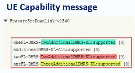
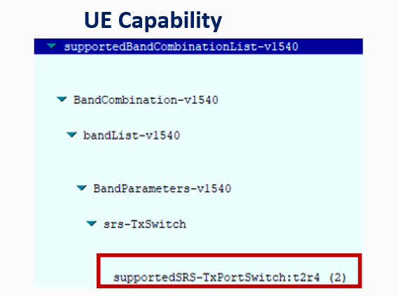
An important point to highlight is that not all users support the additional DMRS, and this can be checked from the UE Capability message, as shown below.
Summary:
Expected Gain: Additional DMRS symbols can help to improve the UE channel estimation performance
Expected Drawbacks: Overhead increase will impact the maximum user speed
Important note: The position of the additional Symbol can be interpreted by the UE through the 3GPP look-up table and not through the Master information block message, as I previously highlighted in my video. (Details will be shared in a separate Post)
Feature 4: SRS Transmission Tuning
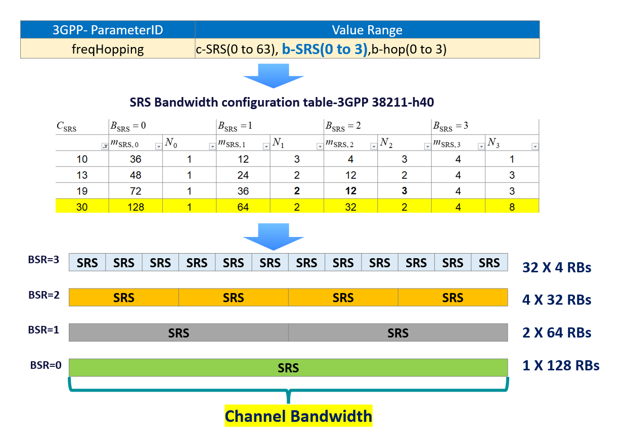
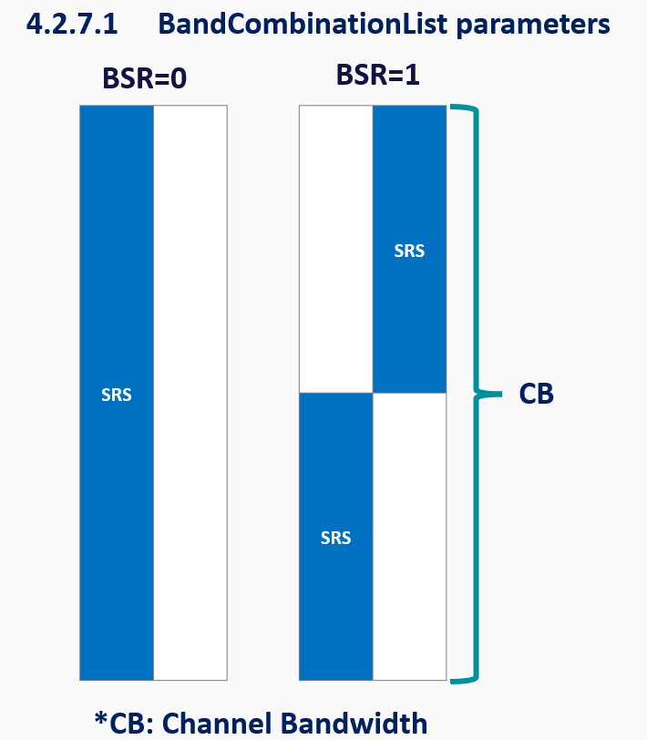
By default, the SRS is being transmitted by the UE through the complete channel bandwidth, which means SRS Power will be distributed over the full channel bandwidth, which might lead to weak SRS coverage in the very cell edge.
As a solution: 3GPP introduced some parameters which can control the SRS BW Transmission. For example, UE can transmit SRS in the Half band instead of the full band, and in that case, this can improve the SRS Coverage by almost double(3dB) as the power will now be distributed over half the bandwidth only.
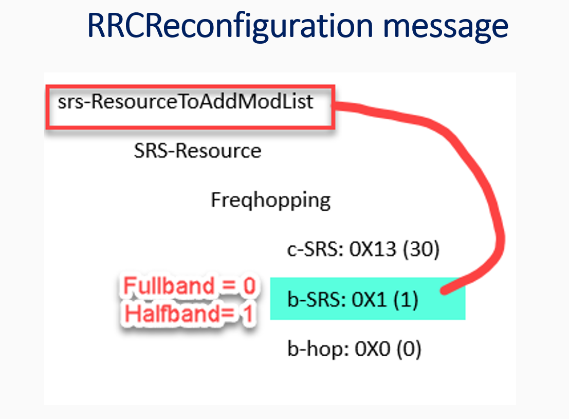
b-SRS parameter under the freqHopping is used to control the SRS BW transmission; below is showing an example for c-SRS = 30 along with different settings of b-SRS(0, 1, 2, and 3). s-SRS refers to the number of allocated Resource blocks for SRS.
SRS Transmission Tuning(UE Capability and Feature verification)
You can verify if UE supports SRS through checking supportedsrs-texportswitch in the UE Capability message as shown below.
SRS Transmission Tuning(UE Capability and Feature verification)
You can verify the current configuration from RRC Reconfiguration message as shown in the below figure:
Notes:
For DL Propagation Channel estimation based on SRS” Channel reciprocity”, the SRS might not quantify DL interference conditions, particularly towards cell edge users where interference levels can be more significant. In this case, UE provides additional info to help characterize the DL interference conditions(CQI, PMI, and so on)
Transmitting SRS across a large BW requires a relatively high UE transmit power. UEs that experience a high path loss can be allocated a smaller SRS BW to increase the received power density.
The drawback associated with smaller BW is a reduced quantity of information regarding the propagation channel. i.e., the BTS is restricted to measuring the propagation channel across a smaller section of the UL BWP.
•If the BTS requires knowledge of the propagation channel across the whole BW part, then multiple SRS TX with Freq hopping are required. For example, the UE would be required to transmit the SRS four times when using 32 Resources
•The requirement to transmit the SRS multiple times increases delay, and there is a risk that the first measurement becomes out-of-date before the last measurement has been completed
The below video explains the same: