5G RLC Complete Guide — Concepts, Modes, Timers, and Troubleshooting (Article + Video)

Introduction
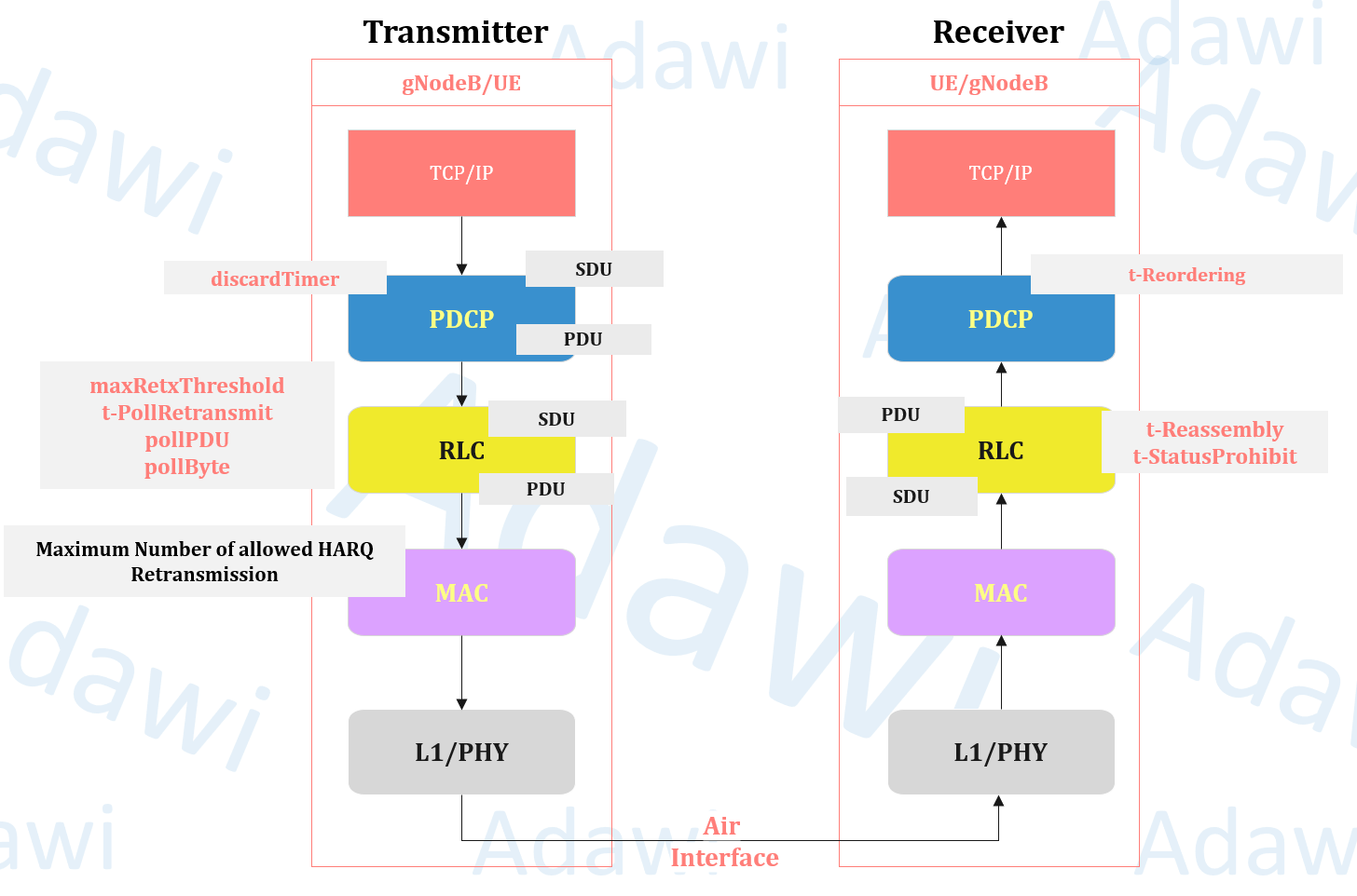
- The Radio Link Control (RLC) layer sits between PDCP and MAC in the user-plane stack.
- Its job depends on the configured mode: it can add headers, segment/reassemble data, and (in AM) retransmit to recover losses.
What you will learn (Scope)
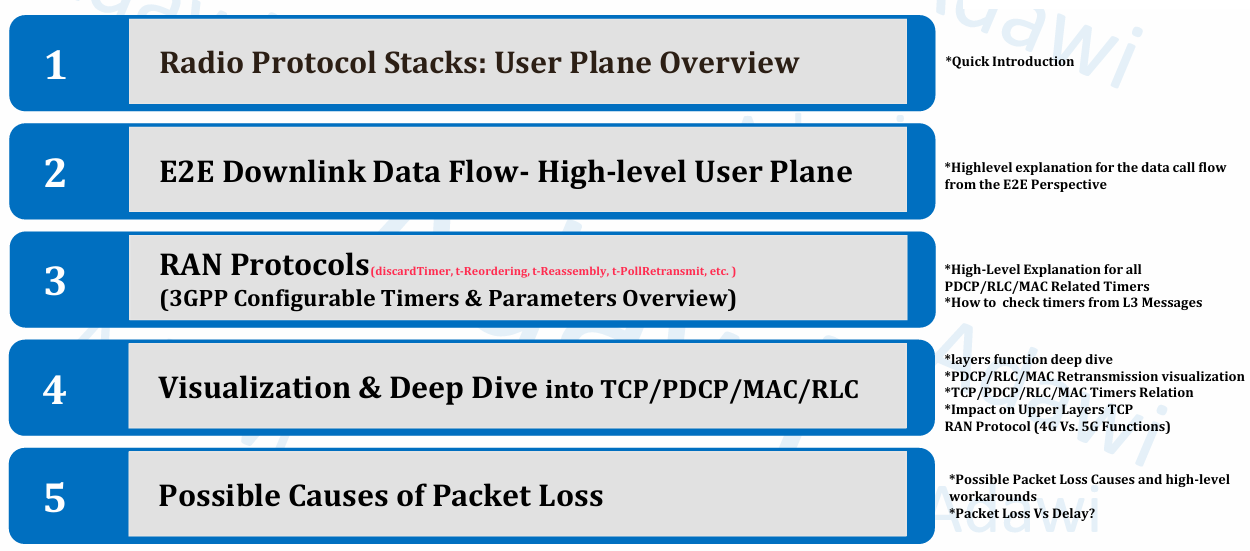
This article will cover:
- Where RLC fits in the E2E user-plane flow
- RLC modes: TM / UM / AM and when each is used
- Core RLC functions (segmentation, reassembly, ARQ, duplicate detection)
- Key RLC headers (D/C, P, SI, SN, SO)
- Polling + STATUS reporting (pollPDU, pollByte, t-PollRetransmit, t-StatusProhibit)
- Receiver behavior (t-Reassembly) and how it triggers status reporting
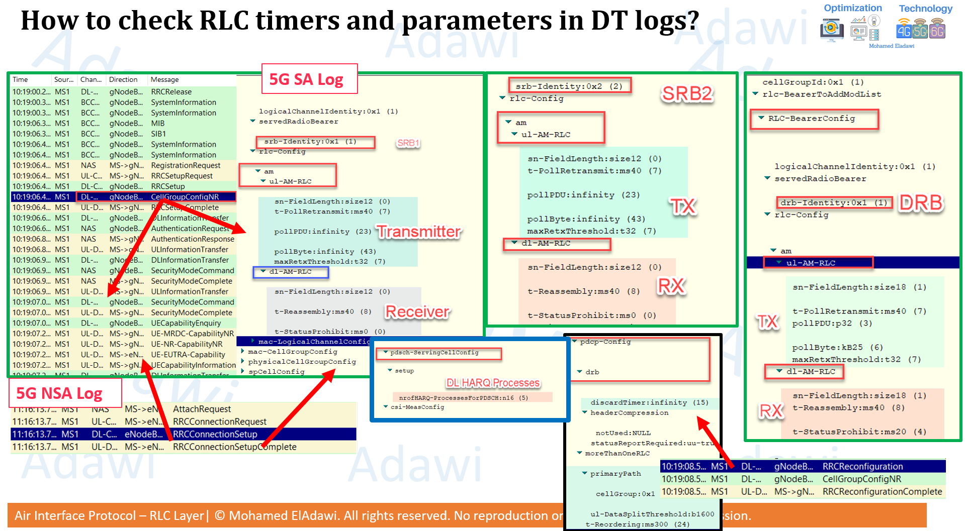
- How to check RLC timers/parameters in DT logs
- Timer alignment with HARQ (t-PollRetransmit vs HARQ)
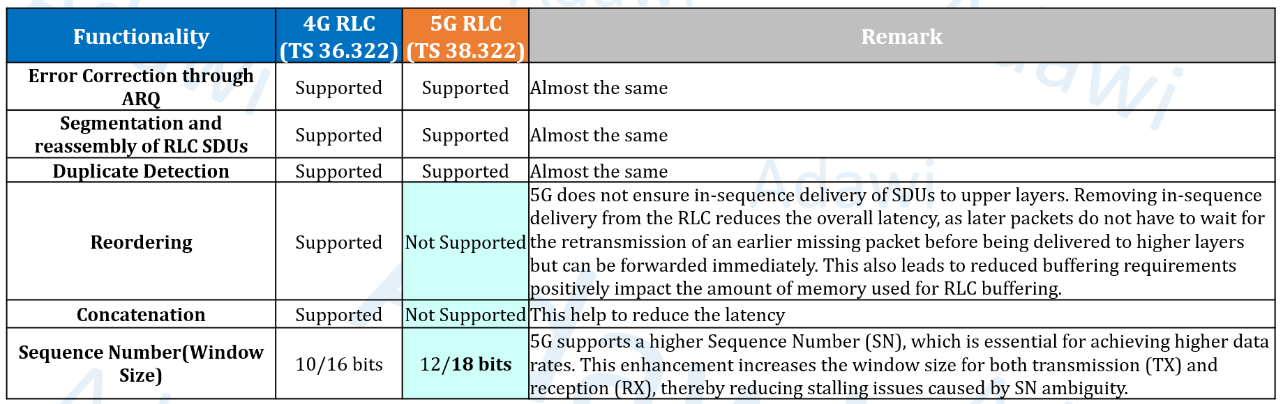
- 4G vs 5G RLC differences (reordering, concatenation, SN/window)
(1) High-level concept
What is RLC?
- RLC is a Layer-2 protocol entity used between PDCP and MAC.
- It processes SDUs from upper layers and produces PDUs for lower layers (with headers when needed).
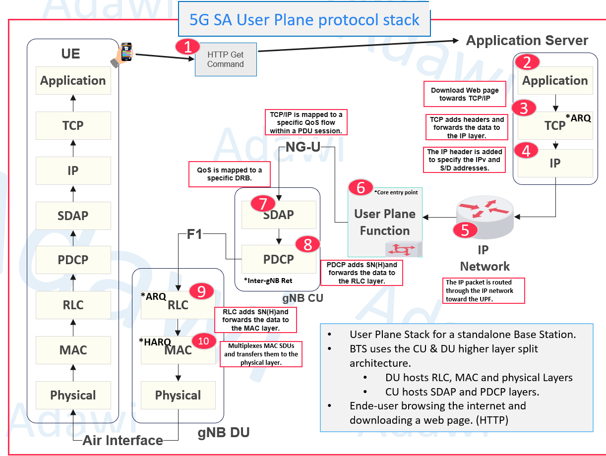
Where it appears in the E2E user-plane flow
- In the high-level downlink flow, PDCP adds PDCP SN (for reordering at receiver),
- then RLC (AM example shown) adds its own SN and handles segmentation/reassembly.
- Then MAC multiplexes and maps to DL-SCH / transport blocks for air transmission.
(2) Main function(s)
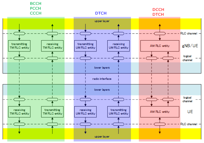
What are the RLC transmission modes?
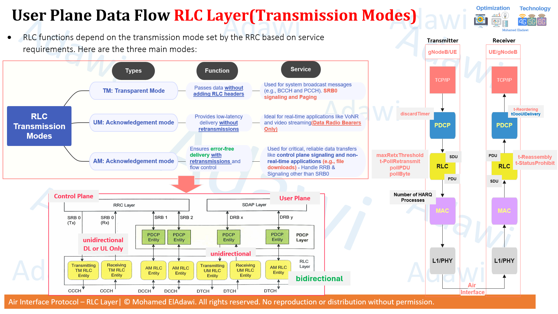
RLC functions depend on the transmission mode set by RRC based on service requirements.
- TM (Transparent Mode)
Passes data without adding RLC headers. Used for BCCH/PCCH, SRB0 signaling, and paging. - UM (Unacknowledged Mode)
Low-latency delivery without retransmissions. Example use case shown: real-time applications like VoNR and video streaming (DRBs only). - AM (Acknowledged Mode)
Ensures error-free delivery using retransmissions and flow control. Example use case shown: control plane signaling and non-real-time applications (e.g., file downloads, Web browsing).
(3) Detailed technical breakdown
3.1 RLC functions by mode (TM / UM / AM)
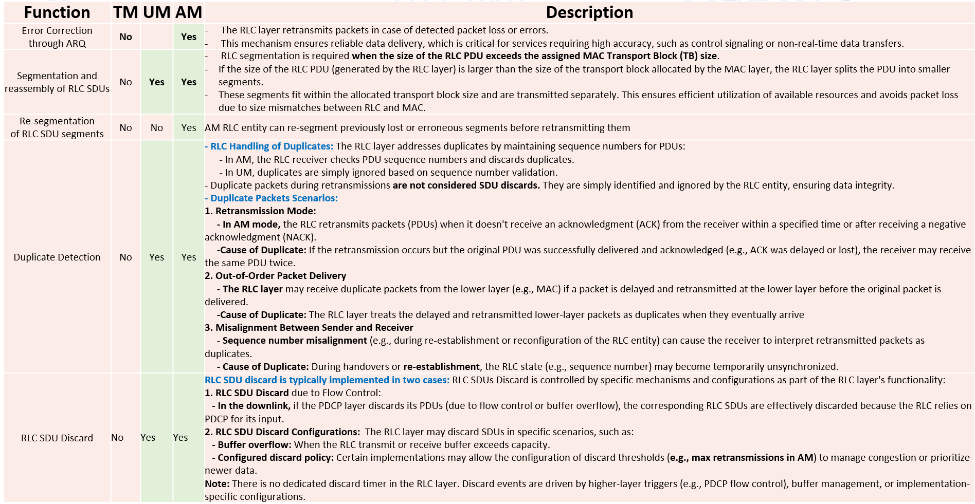
The deck summarizes which functions exist in each mode.
- Error correction through ARQ: only in AM
- Segmentation and reassembly: in UM and AM
- Re-segmentation: in AM
- Duplicate detection: in AM
- Other items on the slide set are shown as part of the RLC function discussion
3.2 Why RLC headers matter (AM header fields)
The key AM header fields and why understanding them helps you connect behavior to timers and network performance.
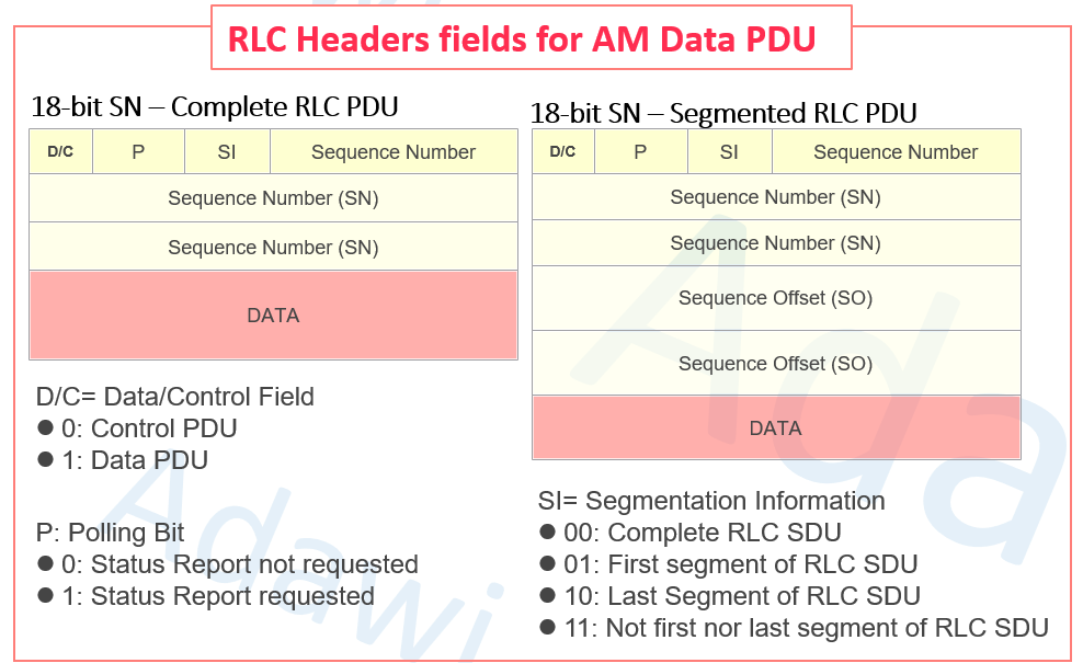
Key fields shown:
- D/C: Data vs Control (STATUS)
- P (Poll bit)
- SI (Segmentation Info)
- SN (Sequence Number)
- SO (Sequence Offset)
3.3 Segmentation and reassembly (SI + SO)
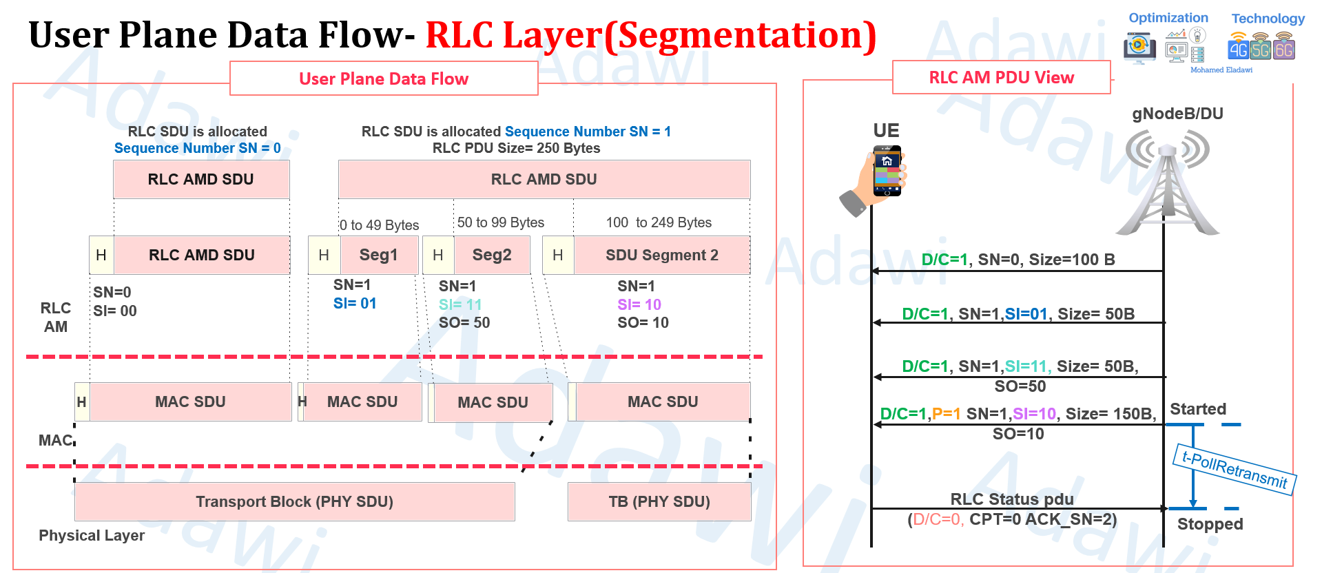
Segmentation happens when the SDU does not fit the available MAC TB size for that transmission opportunity.
- MAC communicates TB size to RLC via UL grants (UL-SCH) or DL allocations (DL-SCH).
- RLC decides whether segmentation is required.
SI (Segmentation Information)
The below lists SI meaning and values:
- 00: Complete SDU
- 01: First segment
- 10: Last segment
- 11: Middle segment
SO (Sequence Offset)
SO indicates the starting byte position of a segment within the original SDU.
It is used during segmentation to help correct reassembly.
Example:
- PDU 1: SN = 0, SO = 0 (First 2000 bytes).
- PDU 2: SN = 0, SO = 2000 (Next 2000 bytes).
- PDU 3: SN = 0, SO = 4000 (Last 1000 bytes).
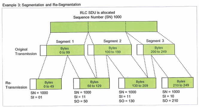
3.4 Re-segmentation (AM)
- The below shows re-segmentation as an AM behavior. It illustrates how the same SN can be retransmitted as re-segmented parts when needed.
- In this example, segmentation is used to create two segments. Subsequently, re-segmentation generates four segments.
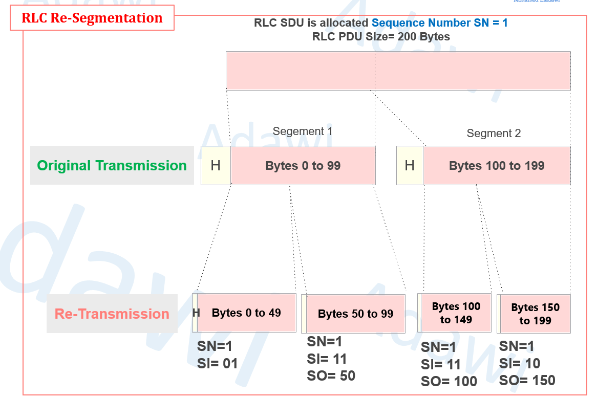
- Another example, will shared below, demonstrates that re-segmentation can combine data from multiple original segments to produce a new set of segments.
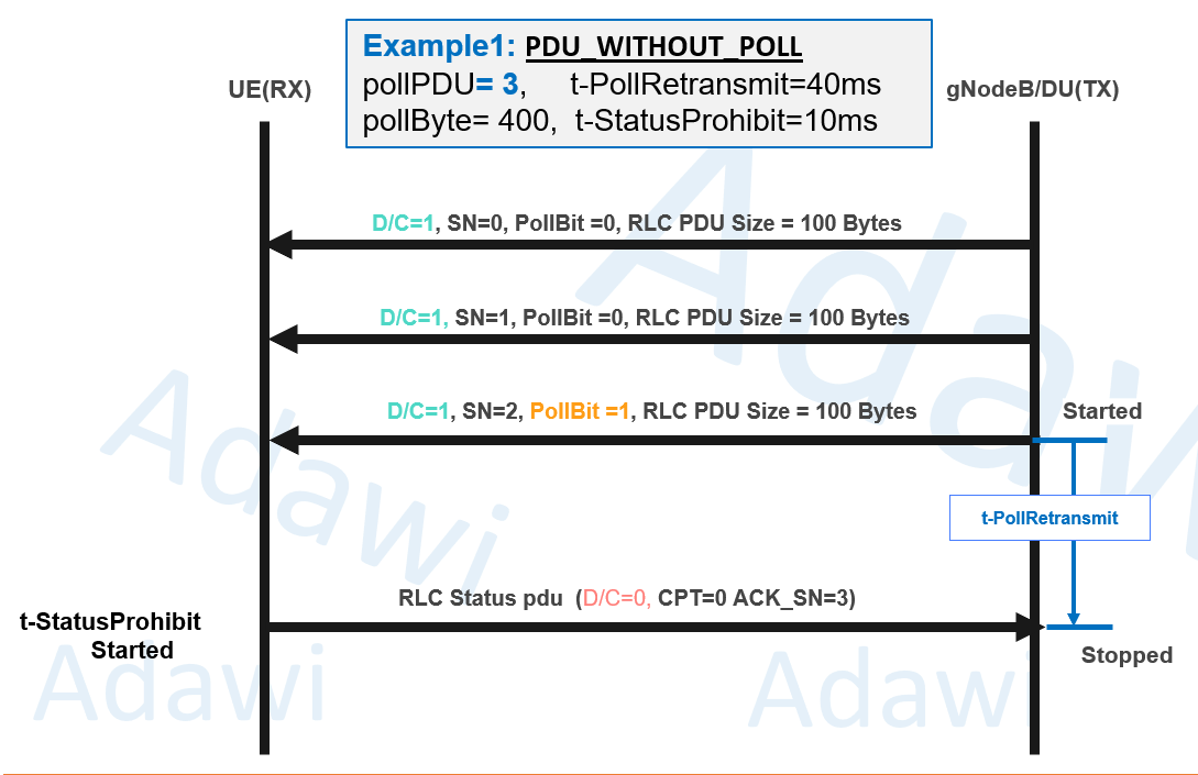
3.5 Polling + STATUS reporting (core AM feedback loop)
AM uses polling and STATUS PDUs for ACK/NACK reporting.
The below lists polling-related parameters:
- pollPDU (PDU-count threshold to trigger polling)
- pollByte (byte-volume threshold to trigger polling)
- t-PollRetransmit (TX waits for STATUS after PollBit=1; on expiry initiates retransmissions + poll retransmission)
Receiver-side control:
- t-StatusProhibit (prohibits frequent STATUS transmissions)
The below set also includes a dedicated “Polling Feature” visualization.
Example 1: PDU_WITHOUT_POLL (pollPDU): After 3 PDU Transmission the transitter requested the received to send RLC Status PDU through setting the PollBit = 1
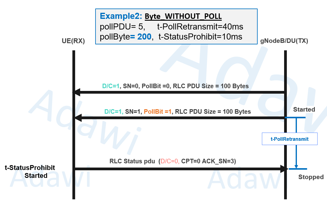
Example 2: Byte_WITHOUT_POLL (PollByte): In this example PollByte is set to 200, while PollPDU = 5, the transmitter requested the received to send RLC Status PDU once the PDU Total Size reached 200 BYTE even the number of transmitted PDUs were only 2
3.6 Retransmission example (STATUS ACK/NACK)
An ARQ example is shown where:
- Multiple PDUs are sent (with PollBit set on a specific SN).
- UE sends RLC STATUS PDU including ACK information (and NACK when applicable).
- Retransmission is driven based on that feedback.
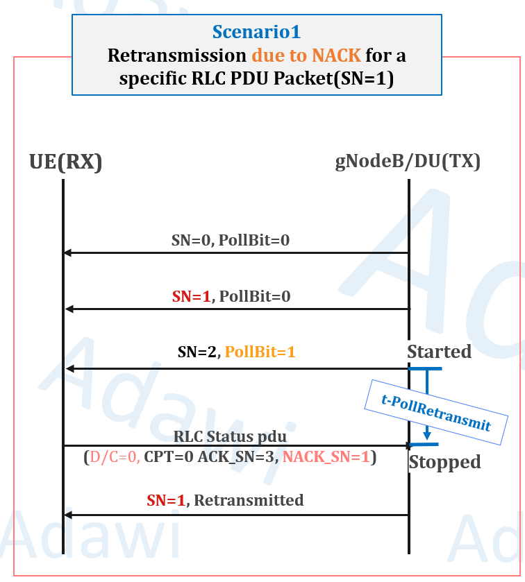
Example 1: Retransmission was driven based on feedback from the UE through sending RLC Status PDU with NACK_SN =1 (the feedback was requested by gNB through setting PollBit=1 → STATUS PDU) indicating that Packet with sequence number 1 (SN=1) was not received, the gNB successfully retransmitted the missing packet
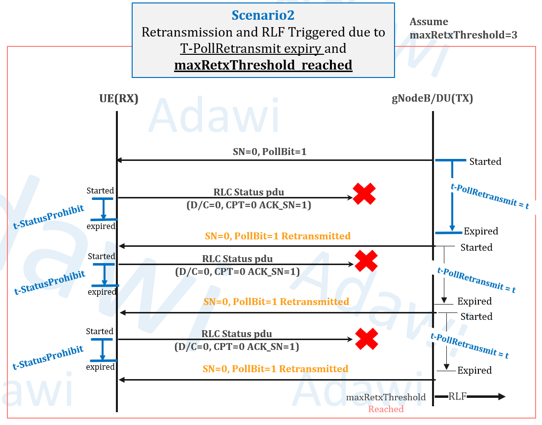
Example 2: The gNB requested the UE TO SEND RLC STATUS PDU for SN=1 (PollBit=1 → STATUS PDU), the UE send the feedback (ACK_SN =1) indicating that he received Packet with SN=0 and is awaiting the next packet with SN=1, however the feedback wasn`t received 3 Times by the gNB, accordingly the Packet with SN=0 was retransmitted 3 times (retransmission is triggered if t-Pollretransmit expired without receiving any feedback from the UE), after the maximum RLC Retransmission was reached (MaxRetThreshold =3). Radio link failure was triggered.
3.7 t-Reassembly (receiver behavior)
t-Reassembly is maintained at the receiving side:
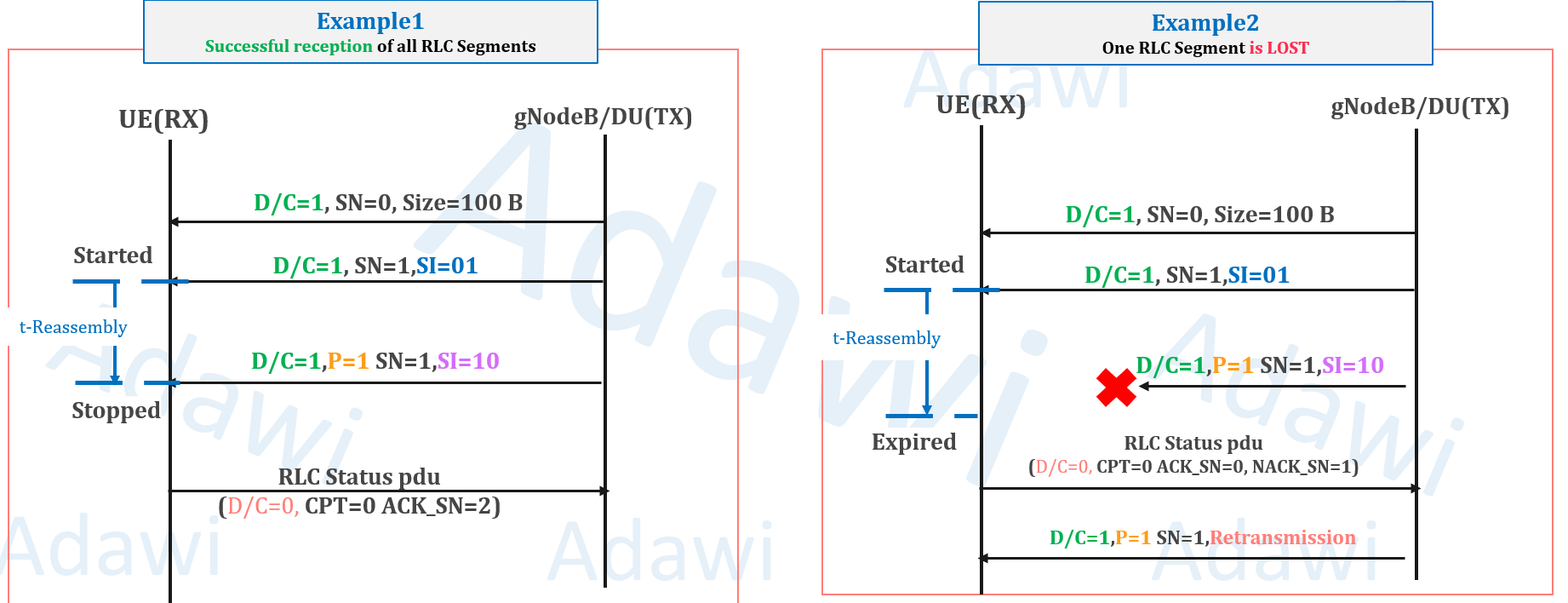
- Started when a segment is received but more segments are pending for that SDU
- Stopped when the SDU is completely received
- At expiry, it triggers status reporting (with STATUS sending controlled by t-StatusProhibit)
- as shown in example2 when the Packet with SN=1 and SI=10 was dropped, the UE requested the gNB to retransmit the missing segment after t-reassembly timer expiry.
3.8 Transmission and reception windows (SN space impact)
Window size generally describes how much data can be transmitted from the sender to the receiver before an acknowledgment is required. The following summarizes the key characteristics of window size:
- Window size depends on SN range
- n-bit SN range is 2^n
- Example values shown: 12-bit SN (0..4095) and 18-bit SN (0..262143)
- The Sequence Number (SN) in RLC is expressed in bits and uniquely identifies RLC PDUs.
- The SN tracks individual RLC PDUs for retransmission and reassembly. Which supports functions like:
- Detecting missing or duplicate packets.
- Maintaining order in data delivery.
- Enabling precise retransmissions in Acknowledged Mode (AM).
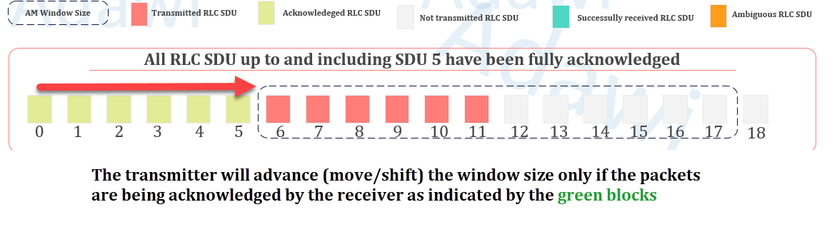
Example 1: No issue is observed here. All transmitted packets (i.e., packets 0–5) were acknowledged by the receiver, so the window advanced to the right, as indicated by the red arrow. However, packets 6–11 have not yet been acknowledged, so the window cannot move further for now. Even so, the transmitter can still send additional packets within the remaining window space (the grey blocks, packets 12–17).
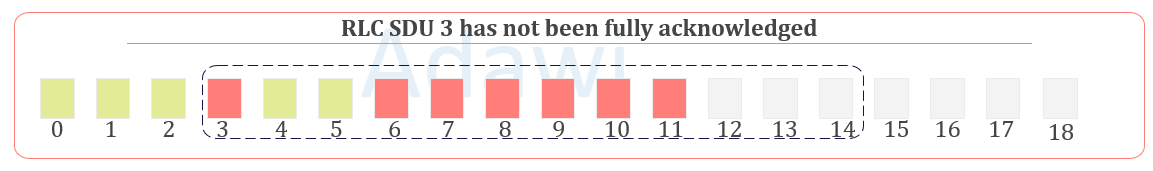
Example 2: Similar to Example 1, the transmitter can still send additional packets within the remaining window space (the grey blocks, packets 12–17). However, the window did not advance to the right because packet 3 has not yet been acknowledged by the receiver.

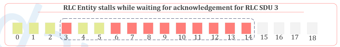
Example 3: Here, the RLC entity stalls (no further packets can be sent by the transmitter) because it is still waiting for an acknowledgment of RLC SDU 3, and the window is already full (i.e., there is no remaining space—no additional grey blocks—within the window).
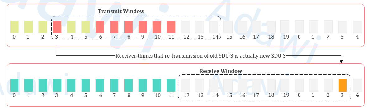
Example 4: The receiver advances its window faster than the transmitter because it actually received packet 3, while the transmitter assumes that packet 3 was missed and needs retransmission. In this example, we assume a very small window size, so the receiver eventually wraps around and resets the window back to 0. When the transmitter later retransmits packet 3 (thinking it was not received), the receiver may interpret it as a new packet rather than a retransmission of the old one. This leads to ambiguous RLC behavior and can result in data stalling.
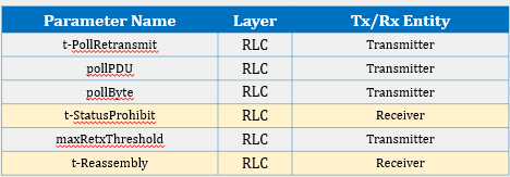
(4) Key parameters (and where to find them)
| Parameter | What it controls | Where it appears (SIB/RRC/DCI/log) | Practical note |
|---|---|---|---|
| rlcSNLength | SN length for AM (12/18) and UM (6/12) | RRC configuration / DT logs | SN size affects TX/RX window behavior |
| pollPDU | PDU-count threshold to set Poll bit | RRC / DT logs | Poll triggers STATUS reporting |
| pollByte | Byte-volume threshold to set Poll bit | RRC / DT logs | Poll triggers STATUS reporting |
| t-PollRetransmit | TX wait time for STATUS after PollBit=1 | RRC / DT logs | Timer alignment with HARQ is discussed in the deck |
| t-StatusProhibit | Limits frequent STATUS transmission | RRC / DT logs | STATUS sending can be gated by this timer |
| t-Reassembly | RX timer for segmented SDU completion | RRC / DT logs | Expiry triggers status reporting |
| maxRetxThreshold | Retransmission limit (failure escalation) | RRC / DT logs | May indicate SDU transmission failure to upper layers |
| nrofHARQ-Processes | HARQ processes (PDSCH/PUSCH) | RRC / DT logs | Used in the same “timer alignment” discussion context |
[Figure 15: How to check RLC timers/parameters in DT logs (5G SA / 5G NSA examples)
(5) RLC Timer alignment with HARQ (walkthrough)
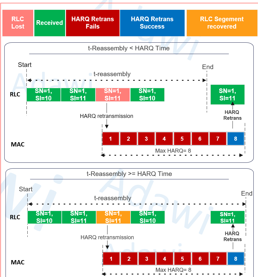
5.1 T-reassembly Vs. HARQ Retransmission
The following provides practical examples to enhance understanding about the relation between T-reassembly and HARQ.
- Segmentation and Reassembly:
- RLC segments SDUs into PDUs based on the MAC Transport Block (TB) size.
- MAC communicates TB size to RLC for proper segmentation.
- Transmission Scheduling:
- MAC schedules RLC PDUs based on priority, resource availability, and QoS.
- RLC ensures PDUs are ready for MAC scheduling.
- Flow Control: RLC controls data flow to avoid MAC buffer overflow or underutilization.
- Feedback and Retransmissions:
- MAC handles HARQ retransmissions; RLC manages higher-layer retransmissions.
- HARQ retransmissions must complete before triggering RLC retransmissions.
- Timer Dependencies: RLC timers (e.g., t-Reassembly) should consider HARQ RTT to avoid conflicts.
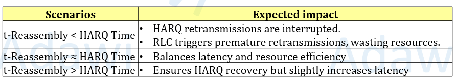
- t-Reassembly Configuration:
- Should be >= Total HARQ Time to ensure HARQ completes before triggering RLC reassembly.
- Avoid overly short timers that disrupt ongoing HARQ retransmissions.
5.2 t-PollRetransmit Vs. HARQ Retransmission
- The key question here is whether there are any relationships or considerations that need to be addressed between the RLC and MAC related Timers and parameters?
- Yes, there should be an alignment when configuration RLC and HARQ related retransmission timers to avoid unnecessary RLC or HARQ Retransmission.
The following provides practical examples to enhance understanding about the relation between t-PollRetransmit and HARQ
- Definitions
- t-PollRetransmit: Timer in RLC to wait for feedback (STATUS PDU) after sending a PollBit.
- HARQ RTT: Time for a HARQ round-trip, typically ~8–12 ms.
- Max HARQ Retransmissions: Maximum retries for a HARQ process, often set to 4.
- Interaction and Timing
- HARQ retransmissions are faster and more resource-efficient than RLC retransmissions. Therefore, the t-PollRetransmit timer must:
- Wait long enough for the MAC layer to complete its HARQ retransmission attempts.
- Avoid expiring prematurely, which could lead to unnecessary RLC retransmissions and signaling overhead.
- Key Timing Calculation: Total HARQ Time = Max HARQ Retransmissions × HARQ RTT.
- Example
- HARQ RTT = 10 ms, Max HARQ Retransmissions = 4.
- Total HARQ Time = 10 ms × 4 = 40 ms.
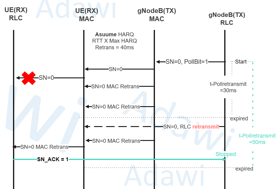
(Example: t-PollRetransmit > Total HARQ Time (e.g., 50 ms).)
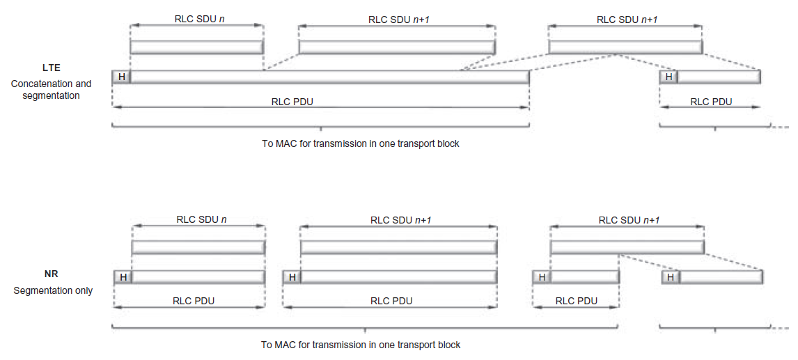
(6) 4G Vs. 5G KPI / design impact
The below highlights the main differences between 4G & 5G RLC:
- 5G removing in-sequence delivery from RLC reduces latency (later packets don’t wait for earlier missing packets).
- It also reduces buffering requirements and memory usage for RLC buffering.
- Larger SN (12/18 in 5G vs 10/16 in 4G shown) increases window size and reduces stalling issues caused by SN ambiguity.
Summary (Key takeaways)
- RLC sits between PDCP and MAC and its behavior depends on the configured mode (TM/UM/AM).
- UM is unacknowledged (the transcript notes a typo on the slide).
- AM reliability is built on polling (PollBit) + STATUS PDUs + ARQ retransmissions.
- Segmentation uses SI and SO to enable correct reassembly at the receiver.
- Key timers include t-PollRetransmit, t-Reassembly, and t-StatusProhibit, plus pollPDU/pollByte and maxRetxThreshold.
- The deck highlights aligning RLC timers with HARQ behavior to avoid unnecessary retransmissions.
- 5G RLC removes reordering and concatenation, improving latency and reducing buffering needs.
Video for the same:
References
- 3GPP TS 36.322 (LTE RLC)
- 3GPP TS 38.322 (NR RLC)
- 3GPP TS 38.331 (RRC configuration referenced in the parameter overview slides)
- 5G NR in Bullets
- The new generation wireless access technology book
- 5G ShareTechNote
- TechPlayon
- Devopedia Foundation