Deep dive into 5G UL SRS- Article

In this article will cover important information about 5G Sounding reference signal. The article will cover the following:
- What is the Sounding Reference Signal?
- What are Sounding Reference Signal Functions?
- How to check SRS UE Capability from UE Logs
- What it means by Antenna Switching?
- SRS Main Parameters Description
- SRS Vs. PMI(CSI-RS) weight obtaining procedure
1- What is the Sounding Reference Signal?
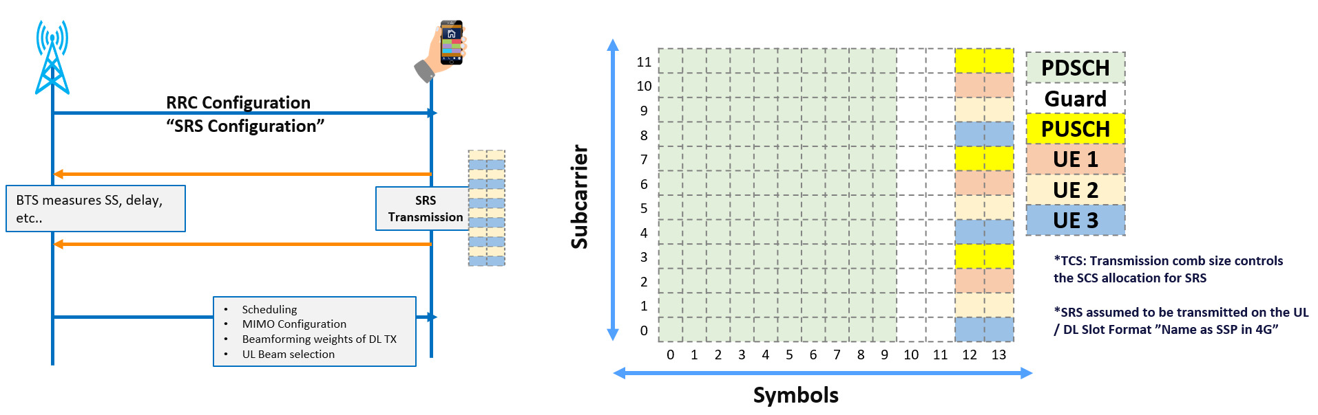
In General, SRS is a reference signal transmitted by the UE, and is measured by the BTS to estimate UL channel propagation, and this in general can be used for many others functions, which will be cover in this article, The below summarizes the main characteristic of 5G SRS:
- The UE transmits the Sounding Reference Signal(SRS) according to the instructions provided by the BTS, and is used by the BTS to measure the UL propagation channel from the SRS.
- An SRS Transmission can occupy 1, 2, or 4 symbols in the time domain; these symbols can be located at the last 6 symbols of a UL Slot.
- An SRS Transmission can occupy up to 272 RBs in the frequency domain, but an individual UE does not transmit the SRS on every subcarrier but select specific SCs based on transmission comb type(TC).
- NR SRS are more flexible compared to 4G, for example 4G SRS were occupying one symbol and was using transmission comb type 2 only , while NR occupy up to 4 symbols and is using transmission comb type 2 or 4.
2- What are Sounding Reference Signal Functions?
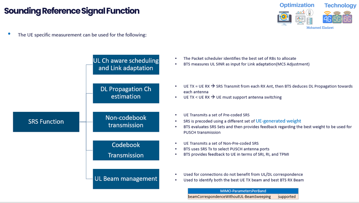
The UE specific measurement can be used for the following:
- UL Channel aware scheduling and Link adaptation
- The Packet scheduler identifies the best set of RBs to allocate.
- BTS measures UL SINR as input for Link adaptation(MCS Adjustment).
- DL Propagation Channel estimation; this only applicable in the TDD System where you have channel reciprocity and require the UE to support SRS Antenna switching.
- Antenna switching simply means if the number of TX Branches is less than the RX Branches within the UE.
- The UE will use the RX branches as a TX to send the SRS. assuming we have 1T2R. This means 2 SRS set will be transmitted through using 1 Tx to switch the signal and send it twice through the two UE RX. this part will be covered in more details below.
- If UE TX = UE RX --> SRS Transmit from each RX Antenna, then BTS deduces DL Propagation towards each antenna.
- If UE TX < UE RX --> UE must support antenna switching.
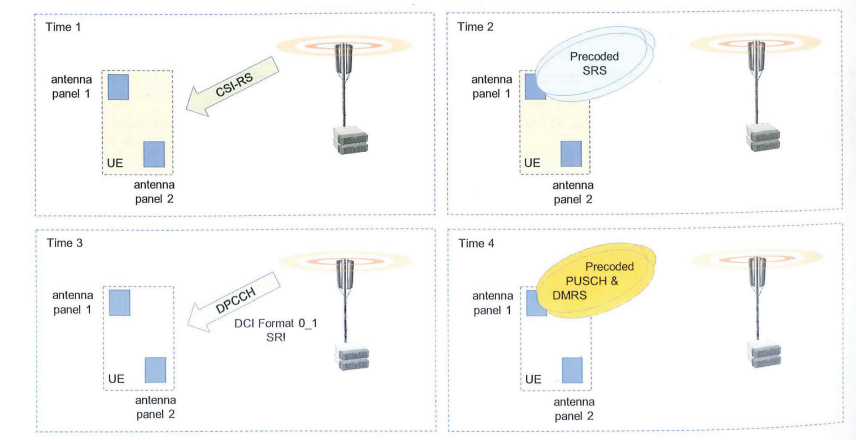
- Non-codebook transmission, This means that the UE measures a DL CS-RS to generate its own precoding weights for the PUSCH. These precoding weights are not constrained to a codebook standardized by 3GPP. Non Codebook transmission relies upon channel reciprocity because the UE determines its UL precoding weights based upon DL measurement
- BTS Sends CS-RS, then UE measures the DL CS RS
- Then UE derive the precoding weights for SRS Resources
- The Transmission of SRS Resources is triggered by PDCCH send by the BTS.
- After UE Transmit SRS based on the resources sent by the BTS. The BTS uses the set of SRS Transmission to determine the number of layers for the PUSCH, The BTS will deduce how many layers is allowed for PUSCH example rank 2 transmission (2 Layers)
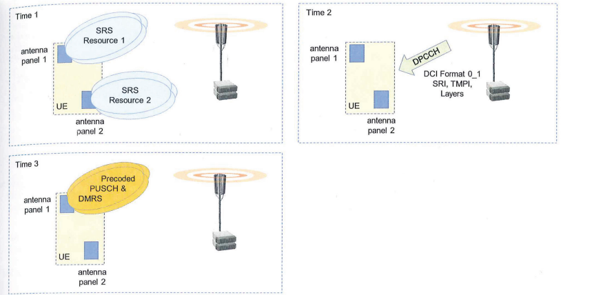
- Codebook transmission, This means that the UE transmits the PUSCH sing precoding weights have which been selected from a codebook standardized by 3GPP
- UE Transmits a set of Non-Pre-coded SRS
- BTS uses SRS Tx to select PUSCH antenna ports
- BTS provides feedback to UE in terms of SRI, RI, and PMI
- UL Beam management; This simply means that SRS can be used for UL Beam management to allow the BTS to select the best UL Beam.
- Used for connections do not benefit from UL/DL correspondence.
- Used to identify both the best UE TX beam and best BTS RX Beam
- UL Beam management is not necessary when the UE Support Beam correspondence, If UL/DL Beam correspondence is supported assumed, i.e. the best beams in the DL direction are also the best beams in the UL direction.
- Beam correspondence UE Capability can be checked from the below message within SRS.

3- How to check SRS UE Capability from UE Logs
- As specified by 3GPP 38306-h40, It defines whether the UE Supports SRS for DL CSI Acquisition is based on the UE SRS Antenna switching.
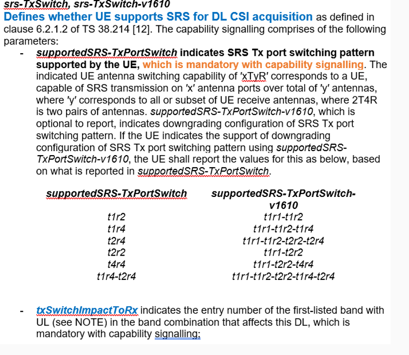
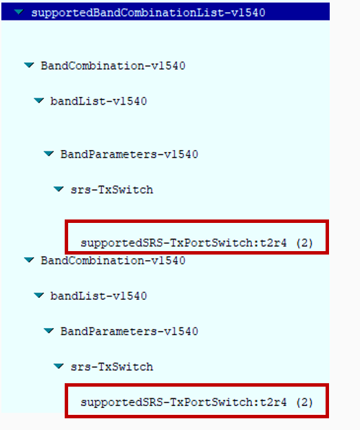
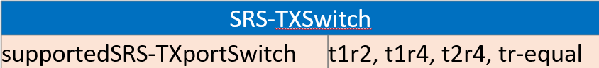
- To verify UE Capability from Logs, You need to look into the following highlighted parameter. "SupportedSRS- TXPortSwitch: TxRx"
4- What it means by Antenna Switching?
- As illustrated in the figure below, the UE switches the SRS transmission to its own 4 RX antennas. In Symbol A, the UE transmits 2 SRS signals, and in Symbol B, it switches the same 2 TX antennas to the remaining 2 RX antennas. (In this example, the UE is assumed to support 2T4R.)
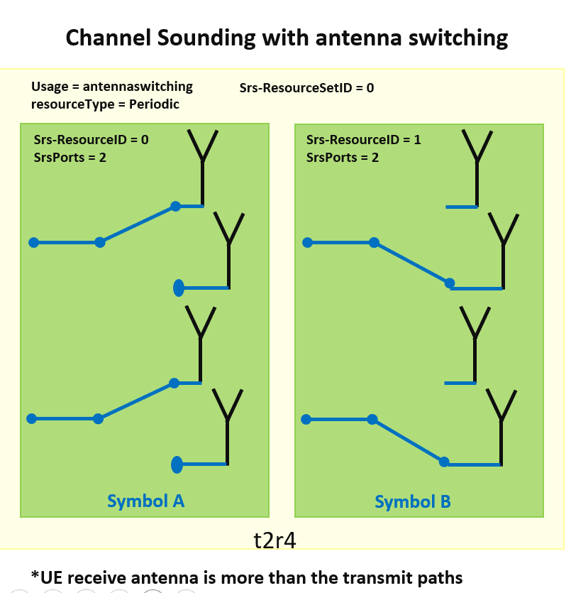
- If the UE can transmit the SRS from each receive antenna, the BTS can utilize the SRS, along with channel reciprocity, to estimate the downlink (DL) propagation channel. This allows the DL propagation channel for each UE receive antenna to be determined.
- The pervious section explained how to check the SRS Antenna switching, which is mainly through the below given element in the UE Capability message. if the UE Capability lack the below, this means antenna switching is not supported and accordingly this particular UE can`t benefit from the channel reciprocity to deduce DL Channel Propagation through SRS.
5- SRS Main Parameters Description
The following 3GPP table summarized some of the main SRS Parameter.
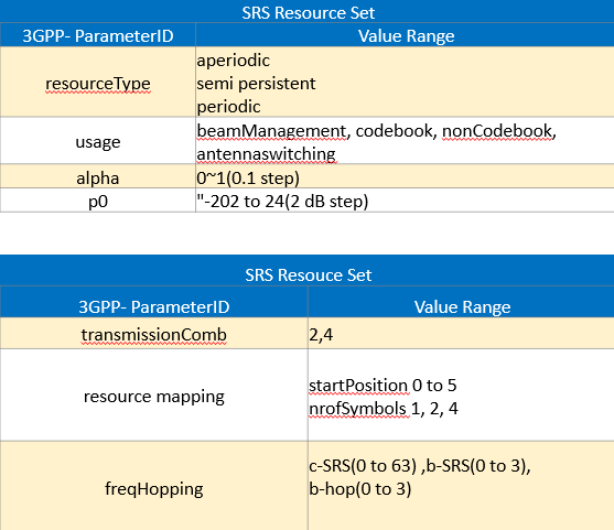
Now, Lets go through these parameters.
SRS Parameters Description:
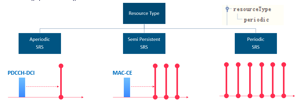
(1) Resource Type:
In general there are 3 different resource types in SRS. Which is periodic, aperiodic and Semi-Persistent. Periodic SRS usually based by default
- A periodic is Triggered using PDCCH DL DCI, and it is event triggered means the BTS will control the transmission of SRS through sending PDCCH-DCI to the users to request UE to send SRS.
- Semi-Persistent SRS Triggered using DL MAC CEs which are transmitted on PDSCH by the BTS.
- Periodic SRS: No Triggering required after configuration. It do not require an activation instruction after the UE receives the SRS resource set configuration.
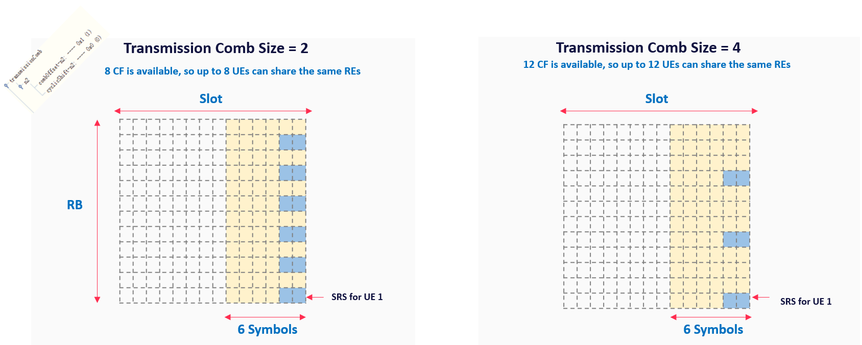
(2) Transmission Comb type
An SRS Transmission can occupy up to 272 RBs in the frequency domain, but an individual UE does not transmit the SRS on every subcarrier but select specific subcarriers based on transmission comb type.
- TX Comb 2 means an individual UE transmits on every second subcarrier. This allows two groups of UE to be frequency multiplexed with a single SC offset
- TX Comb 4 increases the frequency domain multiplexing capability but reduces the quality of the SRS. Because the UE will transmit the SRS at less number of Subcarriers
- UE sharing the same transmission comb are code multiplexed by allocating different cyclic shifts
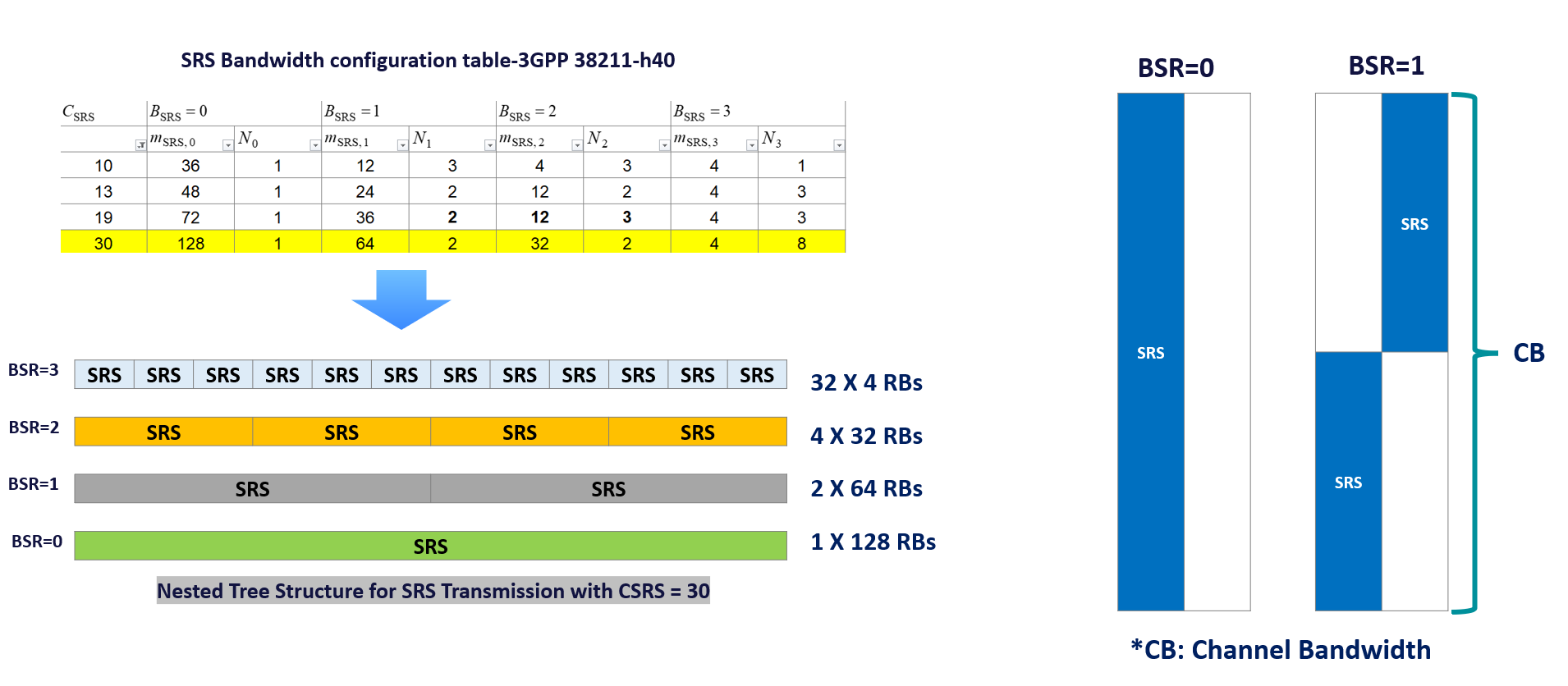
(3) freqHopping(c-SRS & b-SRS)
- Transmitting SRS across a large BW requires a relatively high UE transmit power. UEs which experience a high path loss can be allocated a smaller SRS BW to increase the received power density and this can be tuned through b-SRS parameters. (See the figure below where the BSRS Parameters changed from BSR = to BSR =1).
- The drawbacks associated with smaller BW is a reduced quantity of information regarding the propagation channel.
- For example the BTS is restricted to measuring the propagation channel across a smaller section of the UL BWP.
- If the BTS requires knowledge of the propagation channel across the whole BW part then multiple SRS TX with Freq hopping are required.
- For example the UE would be required to transmit the SRS four times when using 32 Resources as shown in the below figure where the BSR =3
- The requirement to transmit the SRS multiple times increases delay and there is risk that the first measurement become out-of-date before the last measurement have been completed.
The Below video explain the above given information.
Sources:
- 5G NR in Bullets.
- 3GPP 38306-h40
- 3GPP 38.214