Illustration about PDCCH's Main function, the Main difference between 4G&5G PDCCH? PDCCH Frequency & Time domain Resource allocation, PDCCH Resource Mapping

What is the primary function of PDCCH?
Before going into details, You just need to understand that PDCCH is the heart of the Air-interface as it is being used to allocate and inform the UE about all the information needed for any service. In addition to this, Proper optimization of the PDCCH resources is one of the most vital parts of either 4G or 5G, As PDCCH congestion, blocking, or coverage/quality issues(High BLER) can have a severe impact on services such as Volte/VoNR Calls and Latency(Ex: Users will wait longer in the queue waiting for the scheduling information in case of congestion or Load imbalance between existing carriers in your network)
5G PDCCH is mainly used to transfer Downlink control information(DCI), which is the same function is 4G.
- DCI Carriers: Downlink grants, Uplink grants & Transmit power Control commands
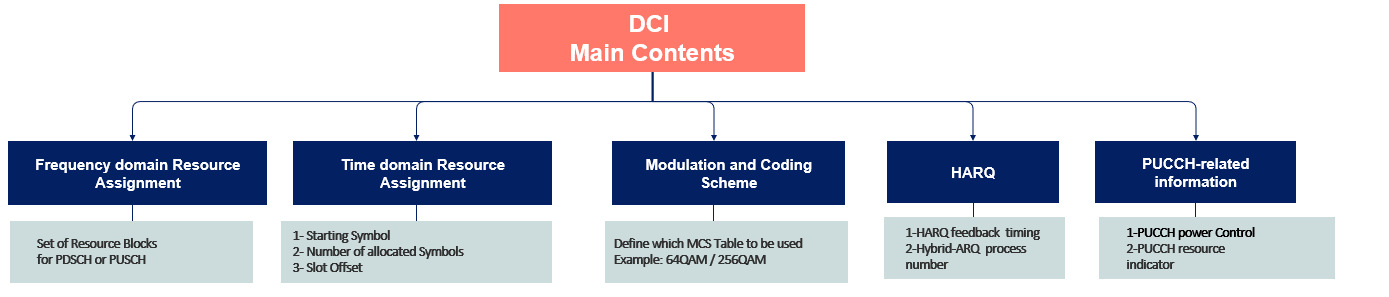
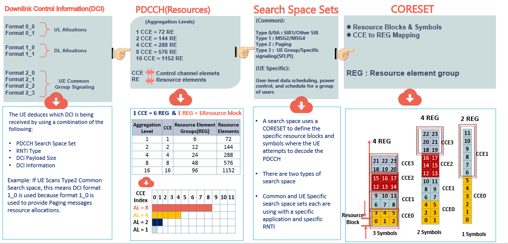
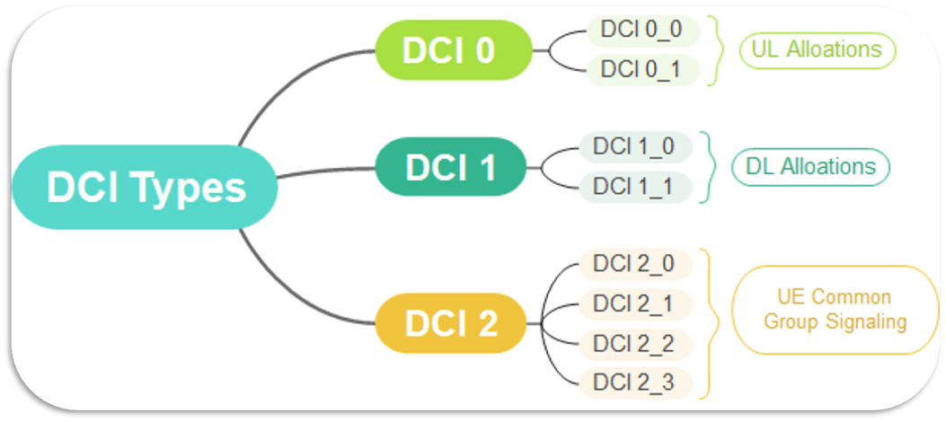
Downlink Control Information (DCI) provides the UE with the necessary Scheduling information, such as DL/UL resource allocation and UE Common group signaling, DCI Provides the resource allocation information for applications such as SIB1, MSG2/3/4, Paging, and UE Data Transfer. The figure below summarizes DCI’s Main contents.
Simply, Resource allocation information means to inform the User about the Set of Frequency resources needed, such as the number of resource blocks required and the location of these RBs in the frequency and time domain; in addition to this, it also informs the User about the MCS Table(64QAM or 256QAM) to be used and other information about HARQ feedback.(Examples added below for visual understanding)
In General, 8 DCI formats are transmitted at the PDCCH and can be deduced by the Users. (Details for the user deduce the DCI will be shared in this article)
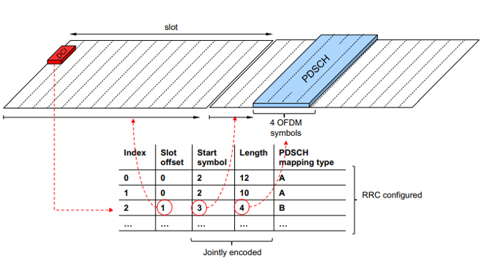
The following picture is an example of time domain resource allocation. The UE decodes DCI information to obtain PDSCH Time domain location, such as the Slot location, Starting Symbol, and the number of Symbols allocated.
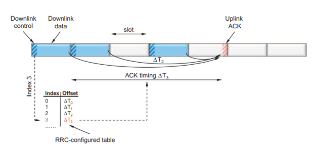
Example for Uplink ACK(HARQ) feedback timing
What are the main differences between 4G & 5G PDCCH?
Before going into the details of about 5G PDCCH, let’s first have a quick insight into the differences between 4G & 5G PDCCH.
In general, NR PDCCH provides the same functions as LTE PDCCH; however, Some new aspects related to PDCCH have been introduced in 5G, such as CORESET, which will be introduced in detail in the following sections.
In LTE, PDCCH control channels are always distributed across the entire system bandwidth.
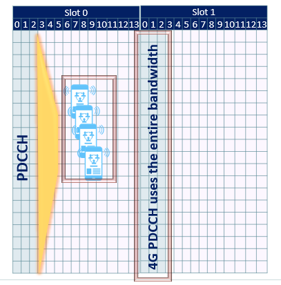
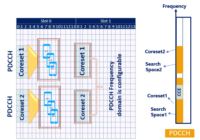
NR PDCCHs are designed to transmit in a configurable control resource set (Called CORESET).
The primary function of CORESET is to identify the resource allocation which is going to be used by PDCCH.
CORSET was introduced in 5G to accommodate the new concept of BWP and to give more control for the frequency resources allocation compared with LTE.
Search Space Sets, Uses specific resource set blocks and symbols where UE blindly attempts to decode PDCCH.(More info will be shared in this article)
How the PDCCH Resources are being mapped from BTS Side, and What are the steps followed by the UE to deduce DCI information?
Well, The below figure shows how the BTS is mapping all related concepts related to PDCCH, such as (DCI, CCE, Search space, and CORESET); the figure looks kind of intimidating, but once you reach the 2nd part of steps followed by the UE to decode PDCCH related information will be able to understand this mapping.
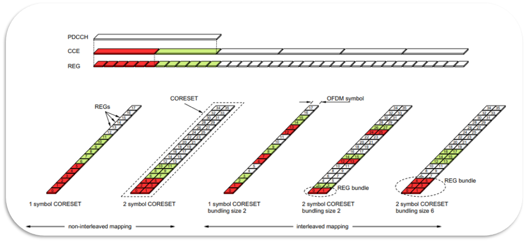
Before going into the details, First, you need to understand that PDCCH occupies a specific number of CCEs, and these CCEs are mapped onto a specific search space according to the content of the DCI; each Search space is mapped onto a specific CORESET. The CORESET defines a set of RBs and the number of symbols (Ops it really looks very complicated). Please jump to the 2nd part related to the steps followed by the Users to decode DCI then try to read this part again once you do)
Have a look into the BTS PDCCH Resource mapping
DCI --> PDCCH(Resources)--> Search Space sets --> CORSET
What are the steps followed by the UE to deduce DCI information?
Well, Let`s try to simplify this time; simply, the UE will follow a reverse order to the resource mapping used by the BTS to obtain DCI(Accordingly will obtain scheduling information)

The UE mainly follows 4 steps to decode DCI.
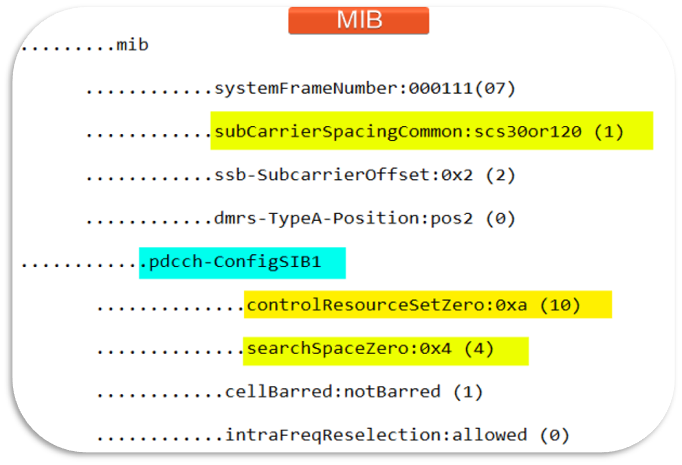
Step 1: UE will decode MIB information to Control Resource Set(CORESET0) information (means number and location of RBs)
MIB Message information and 3GPP Specified table will be covered in the end of this article in the frequency/time domain resource allocation methods
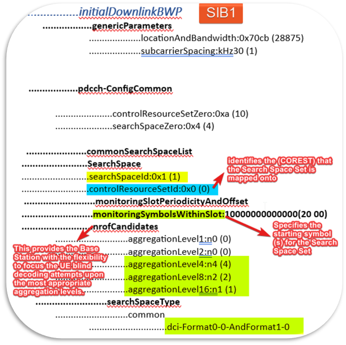
Step 2: UE will decode SIB1 to obtain Search Space information ID, Aggregation Levels, and DCI mapping; each Search Space/DCI Type is equivalent to a specific application information such as Other System information(OSI), MSG2, MSG3, MSG4, and paging information, or it will decode RRC reconfiguration message in connected mode to obtain Search space information related to UE Data Transfer information.
Step 3: based on the search space type and information, the UE will be able to locate CCE allocation methods
Step 4: Once the UE decoded DCI, all the needed scheduling information will be acquired and will be able to start any service.
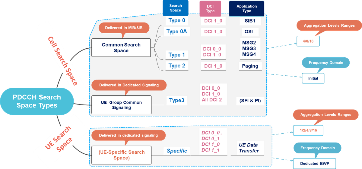
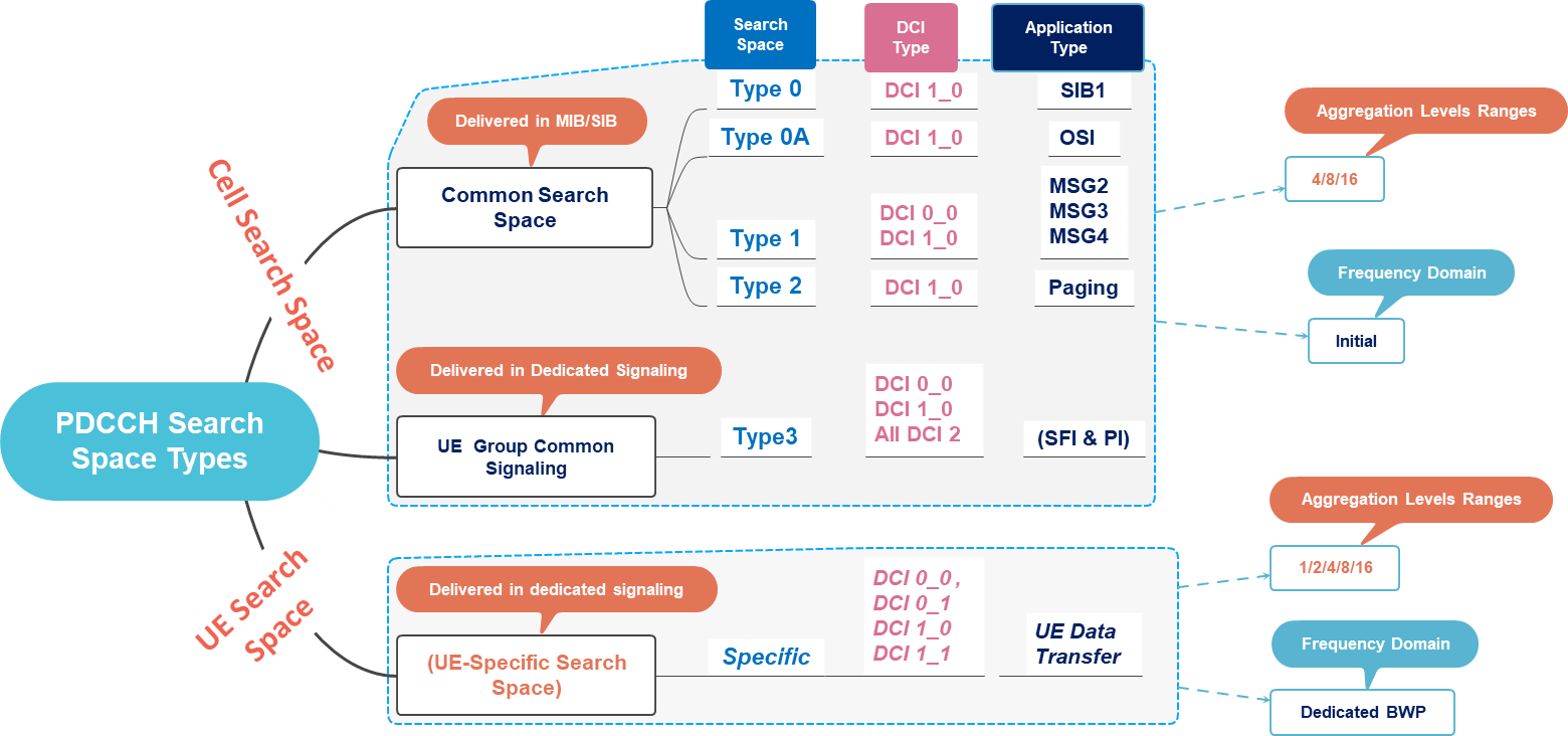
As a summary, Once UE Scans Search Space to be able to deduce the required DCI Format and application type; the following figure covers the details regarding Search Spaces types, mapping with DCI Format and application type, required aggregation levels range, and Messages carrying Search Space resources.
Frequency & Time domain Resource allocation
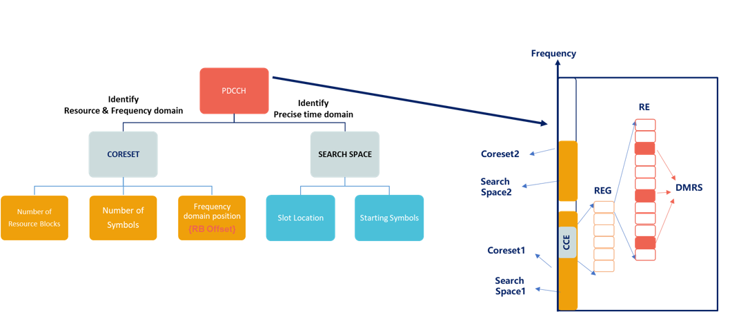
gNB transmits PDCCH using resource elements belonging to a Control Resource Set(CORESET).
CORESET defines the following:
- Number of Resource Blocks
- Number of Symbols
- Frequency Domain Position of CORESET/PDCCH relative to SSB
A Search Space uses CORESET to define the specific Resource Blocks and Symbols where the UE attempts to decode the PDCCH.
The Frequency & Time domain position of the PDCCH is identified by CORESET & SEARCH SPACE(Information included in MIB)
Frequency domain allocation(SEARCHSPACESET0 -SIB1)
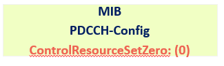
Frequency domain: (1) MIB Message and 3GPP Specified table
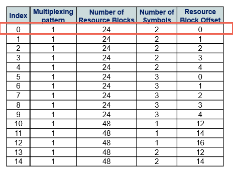
gNB transmits core information element inside MIB message called SEARCHSPACEZero which is used as a pointer within 3GPP Specified tables to identify Frequency & Time domain Positions
Where Number of RBs define the number of resource blocks allocated for PDCCH
The number of Symbols defines the number of symbols allocated for PDCCH
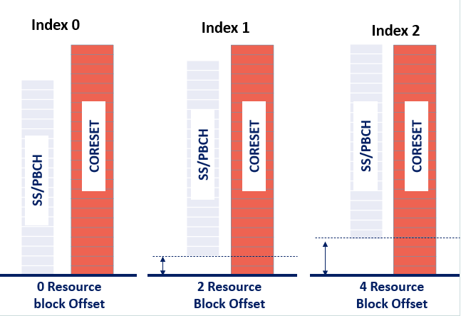
Resource Block Offset: Defines the CORESET location in the frequency domain respect to the SSB frequency domain
Frequency domain: (2) Illustration for Locating CORESET Frequency Position
(1) Time domain allocation(SEARCHSPACESET0 -SIB1)
gNB transmits core information element inside MIB message called SEARCHSPACEZero which is used as a pointer within 3GPP Specified tables to identify Frequency & Time domain Positions

Where Index2 :
0 =2 Means the start Slot will be 2 as the offset is given relative to the start of the frame
M = 1: This means we will have one Search space per slot in the first SSB Transmission
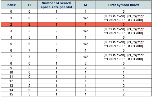
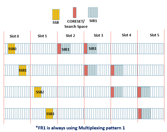
(2) Time domain: Illustration for Locating CORESET/Search Space-Time
Assumptions Used:
- 4 SSBs starting duration 2,8,16,22
- 0”Search space slot offset” = 2
- M” Search space sets per slot = 1
- CORESET Symbols”Duration” = 2
Please feel free to highlight and drop a comment if any of the information provided here still is not very clear, so I can start preparing a YouTube video to simplify this subject, as much as I can if needed.