5G SSB Explained: Cell Search, Frequency Positioning, Beam Sweeping, and Overhead - Article


Introduction
The Synchronization Signal Block, or SSB, is one of the first NR signals a UE must detect before it can access a 5G cell. It is the entry point for synchronization, cell identification, essential broadcast information, and beam-based initial access.
If the UE cannot find and decode SSB correctly, it cannot continue toward MIB decoding, SIB1 acquisition, random access, or stable mobility behavior. That is why SSB design directly affects accessibility, access delay, coverage, and beam performance.
Content
This article will cover:
- What SSB is and why it matters
- The main functions of SSB during cell search, initial access, and mobility
- SSB frequency location identification methods
- Frequency-domain resource allocation and how the UE locates SSB inside the channel bandwidth
- Time-domain resource allocation of SSB
- SSB beam sweeping and beam selection
- Main SSB parameters and where to find them
- SSB overhead calculation
- Questions and Answers
- Summary and key takeaways
Section 1
What SSB is and why it matters
SSB stands for Synchronization Signal Block. It is the physical block used by the UE to detect a 5G NR cell, achieve downlink synchronization, identify the cell, and start reading the essential broadcast information needed for initial access.
At a high level, SSB contains:
- PSS for primary synchronization
- SSS for secondary synchronization
- PBCH for broadcasting the MIB
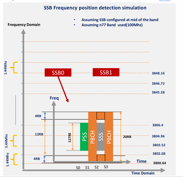
From a resource point of view, the SSB occupies 20 RBs over 4 OFDM symbols.
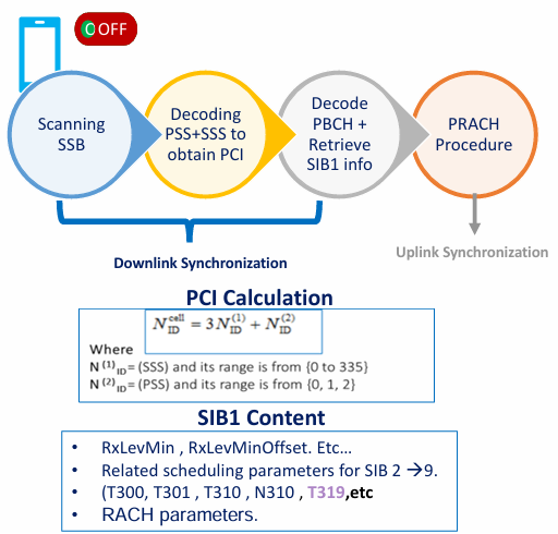
A simple way to understand its role is this:
- the UE scans the band to find the SSB frequency location
- once detected, it decodes PSS and SSS to obtain synchronization and the physical cell ID
- then it decodes PBCH to obtain the MIB
- after that, it can continue toward SIB1 acquisition and PRACH
SSB is therefore not just another physical signal. It is the UE’s first practical doorway into the cell.
Section 2
The main functions of SSB during cell search, initial access, and mobility
The main role of SSB is to allow the UE to find and enter the cell. In practice, that role expands into several important functions.
Cell search
During initial cell search, the UE scans the target band until it detects the SSB frequency location. Once it finds the correct position, it starts decoding:
- PSS
- then SSS
- then PBCH
This sequence enables the UE to move from blind scanning toward actual cell acquisition.
Synchronization and cell identification
PSS and SSS allow the UE to align with the cell timing and derive the physical cell ID. Without this step, the UE still does not know which cell it is listening to.
Broadcast information for initial access
After synchronization, the UE decodes PBCH to obtain the MIB. The MIB then provides the minimum information needed to continue toward the next steps of access, including SIB1 acquisition and common-channel interpretation.
Mobility support
SSB is also important during mobility, not only during initial power-on. It supports:
- cell reselection
- handover-related behavior
- beam-based mobility measurements
That is why SSB is relevant both for accessibility and for mobility robustness.
Relation to PRACH
SSB is part of the downlink preparation phase before the UE starts uplink access. In simple words, the UE first finds and understands the cell in downlink, then moves toward PRACH for uplink synchronization.
Section 3
SSB frequency location identification methods
One of the first questions in SSB design is: how does the UE know where the SSB frequency is located?
In general, two main methods are used:
- ARFCN / channel raster
- GSCN / synchronization raster
These two methods serve the same big purpose, but they are used differently depending on the scenario.
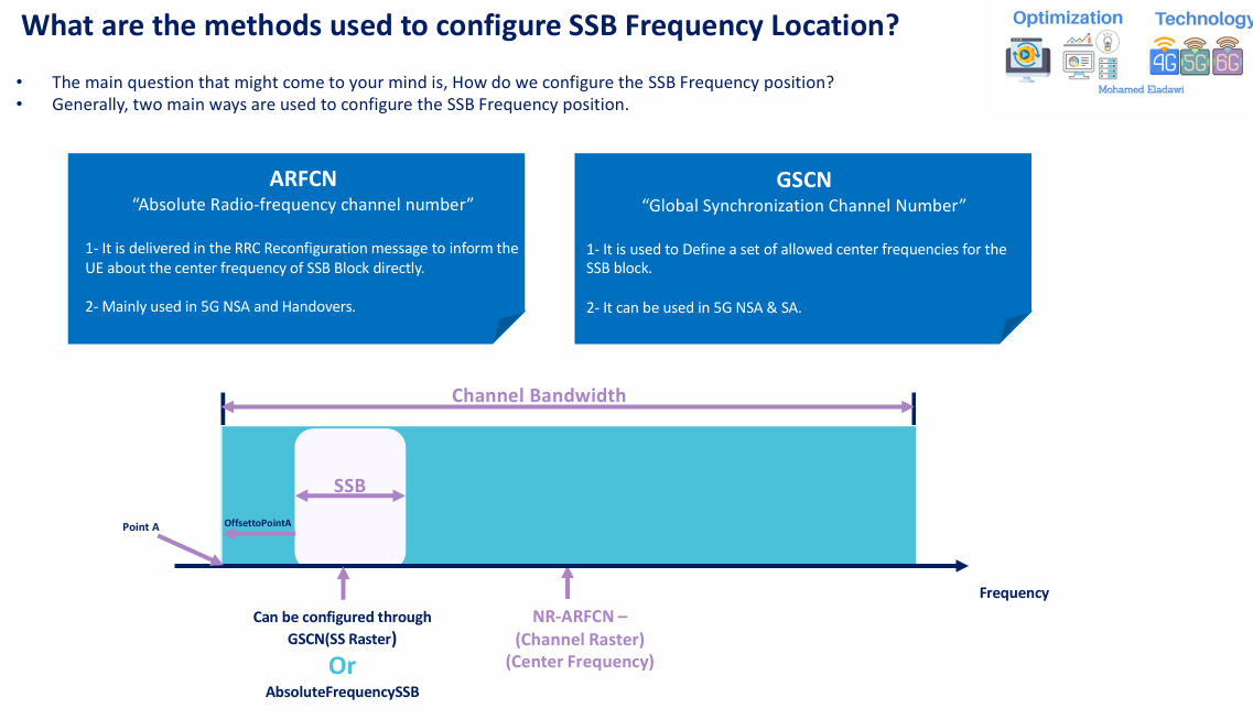
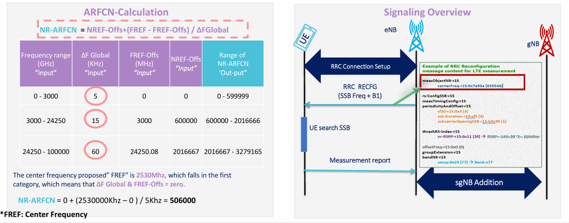
3.1 ARFCN and channel raster
ARFCN stands for Absolute Radio Frequency Channel Number.
In this method, the SSB frequency position is delivered more directly to the UE through signaling. This is commonly associated with:
- 5G NSA
- handover-related dedicated signaling
- RRC Reconfiguration
At a high level:
- ARFCN is used to calculate the center channel frequency
- it can also be used to define the absolute SSB frequency
- it offers a relatively fine scan granularity compared with synchronization raster
A practical example often used is:
- proposed center frequency = 2530 MHz
- this falls in the first ARFCN range
- resulting NR-ARFCN = 506000
This approach is useful when the UE receives the relevant frequency information more directly, so it does not need to perform a broad blind search.
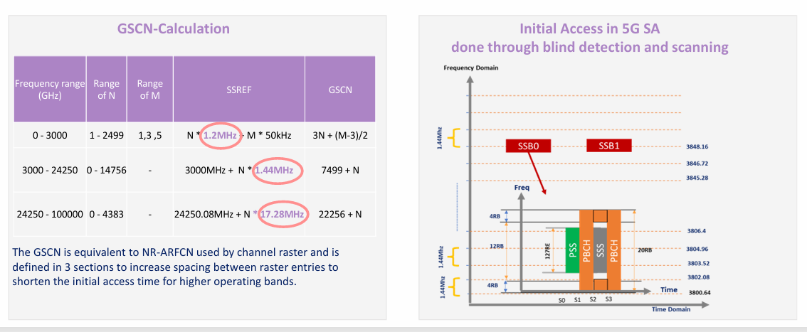
3.2 GSCN and synchronization raster
GSCN stands for Global Synchronization Channel Number.
This method defines a set of allowed center frequencies for the SSB block. It is especially important because it reduces the number of candidate positions the UE needs to check during band scan.
At a high level:
- GSCN can be used in both NSA and SA
- it is particularly important in 5G SA
- it uses a lower-resolution synchronization raster to make blind detection faster and more efficient
In simple words:
- ARFCN is a more direct frequency indication approach
- GSCN is a guided blind-search approach based on allowed synchronization positions
This is why GSCN is closely linked to initial access efficiency, especially when the UE must scan the NR carrier without prior dedicated frequency guidance.
Section 4
Frequency-domain resource allocation and how the UE locates SSB inside the channel bandwidth
Finding the SSB frequency is only the first step.
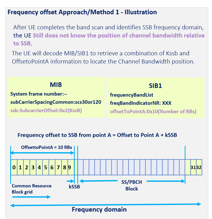
After the UE detects the SSB, it still does not automatically know where the full channel bandwidth is located relative to that detected SSB. Additional information is needed so the UE can place the SS/PBCH block correctly inside the carrier resource grid.
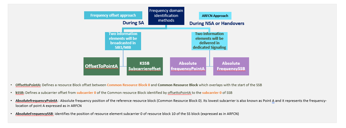
In general, two approaches are used:
- a frequency offset approach
- an absolute frequency approach
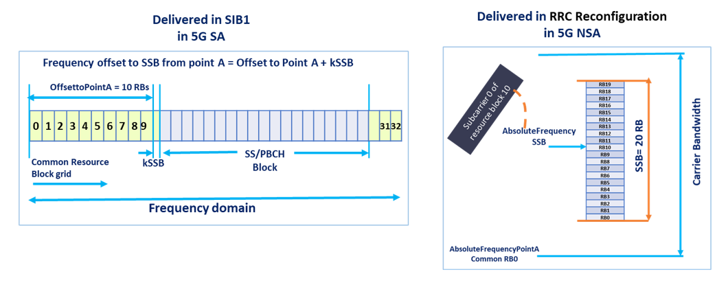
4.1 Offset to Point A and kSSB
This is the frequency offset approach.
In this case, the UE uses a combination of:
- OffsetToPointA
- kSSB
These values are used to locate the SSB relative to the common resource-block grid.
What does OffsetToPointA mean?
OffsetToPointA defines the RB offset between Common RB0 and the common RB that overlaps with the start of the SSB.
What does kSSB mean?
kSSB defines the subcarrier offset from subcarrier 0 of the common RB identified by OffsetToPointA to subcarrier 0 of the SSB.
So, in simple words:
Frequency offset to SSB from Point A = OffsetToPointA + kSSB
This is a very important concept because the UE may detect the SSB first, but it still needs these offsets to understand where the full channel bandwidth sits relative to that SSB.
The UE retrieves these values through the common signaling path, mainly from MIB and SIB1.
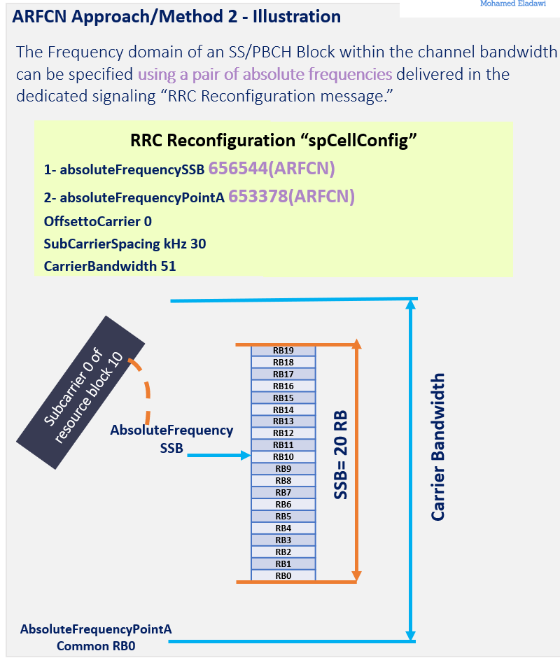
4.2 AbsoluteFrequencySSB and AbsoluteFrequencyPointA
This is the absolute frequency approach.
In this case, the frequency position of the SS/PBCH block is specified using a pair of absolute frequencies:
- AbsoluteFrequencySSB
- AbsoluteFrequencyPointA
What does AbsoluteFrequencySSB mean?
It identifies the frequency location of the SSB.
What does AbsoluteFrequencyPointA mean?
It identifies the absolute frequency position of the reference resource block, also known as Point A or Common RB0.
This pair is commonly delivered in dedicated signaling, such as RRC Reconfiguration, and is especially relevant in NSA and some mobility-related procedures.
A simple way to compare both methods is:
- OffsetToPointA + kSSB = relative positioning method
- AbsoluteFrequencySSB + AbsoluteFrequencyPointA = absolute positioning method
Both methods solve the same problem: helping the UE understand where the detected SSB sits inside the carrier bandwidth.
Section 5
Time-domain resource allocation of SSB
SSB is not only defined in frequency. It is also allocated in the time domain.
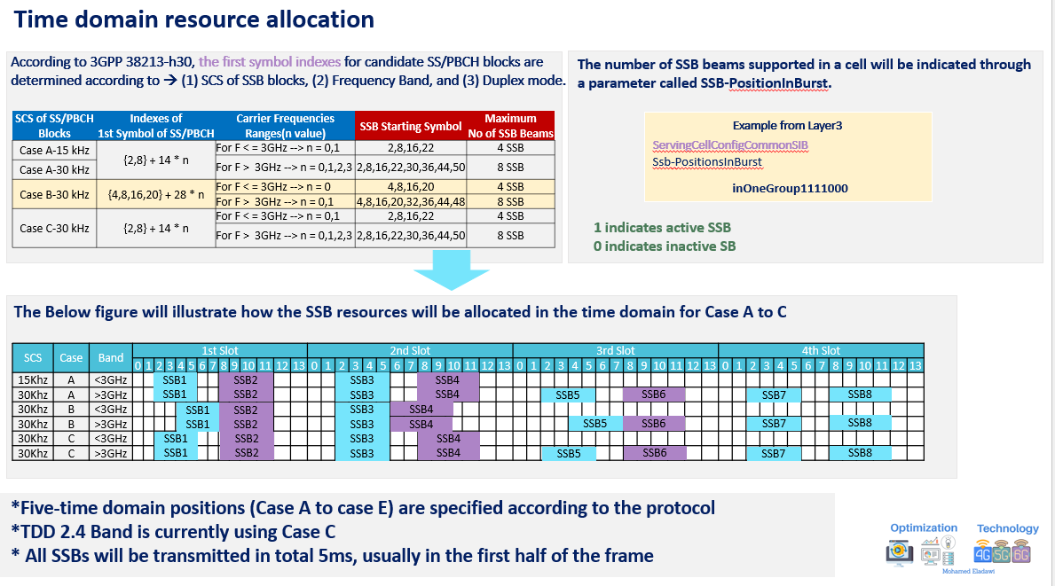
The first-symbol indexes of candidate SS/PBCH blocks depend mainly on:
- the subcarrier spacing of the SSB
- the operating frequency range
- the duplex mode
- the applicable time-domain case
The most commonly illustrated cases here are Case A, Case B, and Case C.
Additional context: 3GPP defines five time-domain cases, from Case A to Case E. The examples below focus on the commonly illustrated Cases A to C.
5.1 Case A
Case A is commonly associated with the symbol pattern:
{2, 8} + 14n
This gives candidate first-symbol positions such as:
- 2, 8, 16, 22 for lower-frequency cases
- 2, 8, 16, 22, 30, 36, 44, 50 for higher-frequency cases
So, depending on the frequency range, Case A can support:
- 4 SSBs
- or 8 SSBs
5.2 Case B
Case B is associated with the symbol pattern:
{4, 8, 16, 20} + 28n
This gives candidate first-symbol positions such as:
- 4, 8, 16, 20
- or 4, 8, 16, 20, 32, 36, 44, 48
So Case B can also support:
- 4 SSBs
- or 8 SSBs
5.3 Case C
Case C follows a pattern similar to:
{2, 8} + 14n
This again leads to candidate positions such as:
- 2, 8, 16, 22
- or 2, 8, 16, 22, 30, 36, 44, 50
In practical deployment notes:
- Case C is commonly associated with some TDD mid-band scenarios
- all SSBs are typically transmitted within 5 ms
- they are usually placed in the first half of the frame
Active vs inactive SSB positions
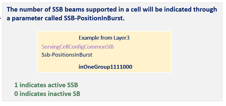
Even when several candidate positions are allowed by the case, not all of them must be active.
The active positions are indicated through:
- SSB-PositionsInBurst
For example:
- 1 means the SSB position is active
- 0 means the SSB position is inactive
This is how the network controls how many SSB beams are actually transmitted.
SSB beam sweeping and beam selection
One of the most important reasons why SSB became even more critical in 5G is its relation to beam sweeping.
This is one of the clearest differences between traditional broad-cell synchronization and modern beam-based NR access.
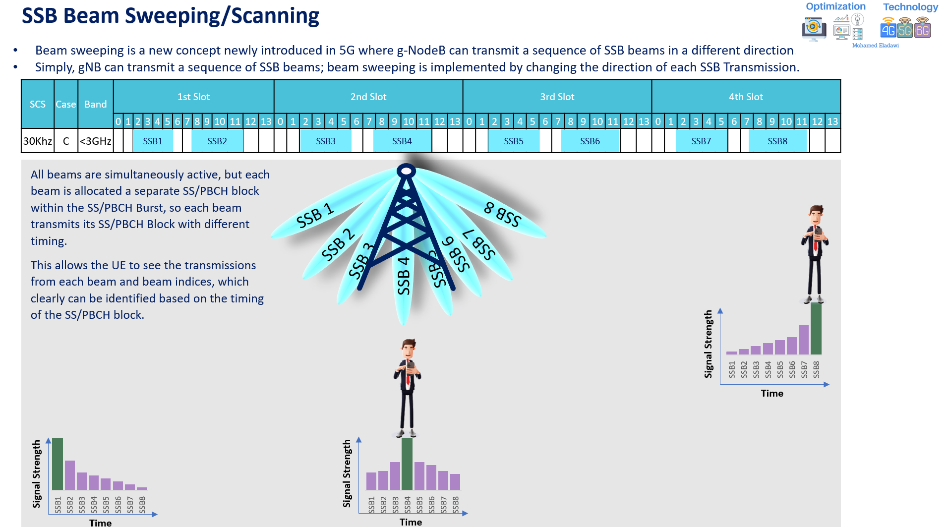
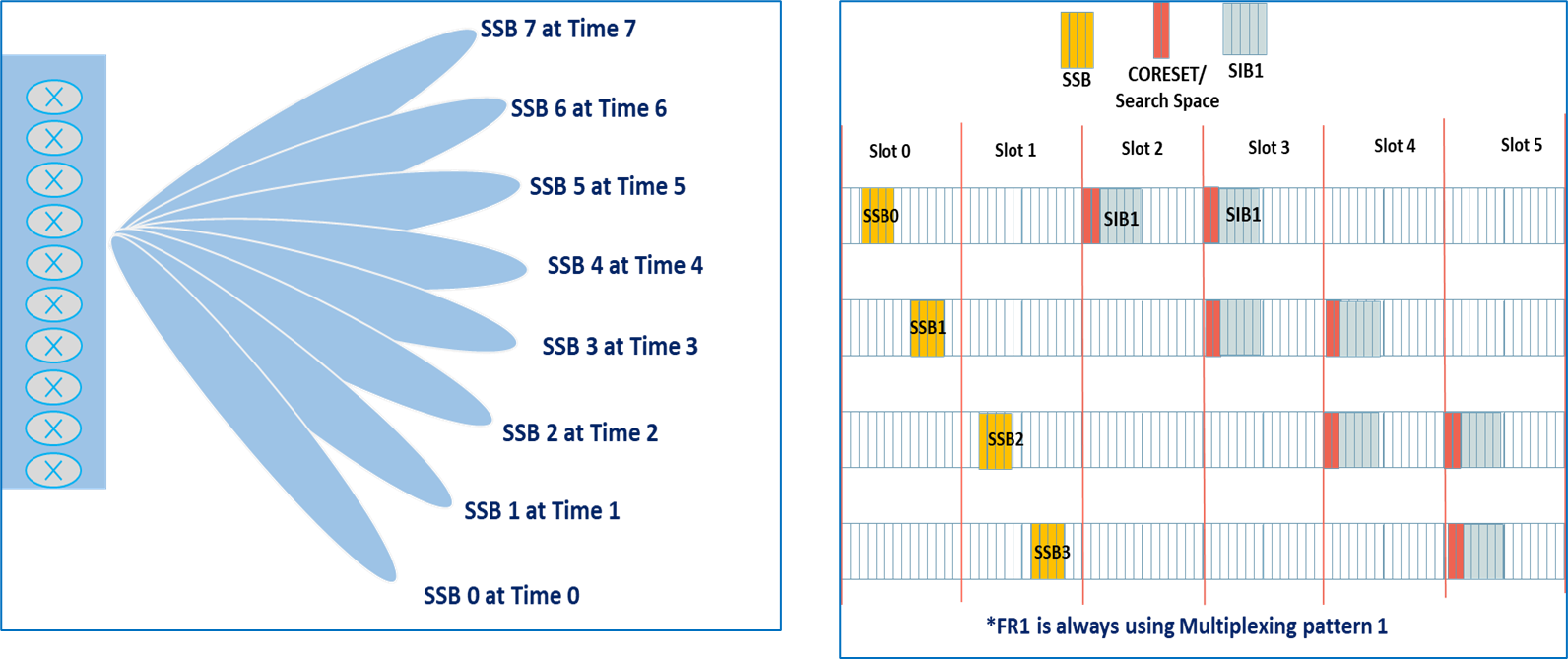
6.1 What beam sweeping means in 5G
Beam sweeping means that the gNB transmits a sequence of SSB beams in different directions.
In simple words:
- the gNB does not transmit only one broad synchronization beam
- instead, it transmits multiple SSBs
- each SSB points in a different direction
This is how the network can cover different users across different spatial directions during initial access.
Although the beams belong to the same SS/PBCH burst, each beam is mapped to its own SS/PBCH block timing. This allows the UE to distinguish between the beams.
6.2 How the UE identifies the best SSB beam
Because each SSB beam is transmitted at a different timing position inside the burst, the UE can identify which beam it is measuring.
The UE then:
- measures the signal strength of the transmitted SSB beams
- compares them
- reports the result
- and the network can select the best beam for access
A simple way to visualize the process is:
- SSB1 may be strongest for one user location
- after the user moves, SSB4 may become stronger
- the network can therefore adapt beam choice based on the reported SSB measurements
This is why SSB beam sweeping is tightly connected to beam-based initial access.
6.3 Advantages and trade-offs of SSB beam sweeping
Main advantages
- better directional coverage
- better beamforming gain
- better expected signal quality and SINR
- better probability that the UE finds a suitable serving beam
Main trade-offs
- more SSB beams increase the occupied broadcast resources
- more SSB beams increase SSB-related overhead
- the associated common-control and broadcast burden can also increase
So beam sweeping brings a clear performance gain, but it must be configured carefully to avoid unnecessary overhead.
Section 7
Main SSB parameters and where to find them
The following parameters are among the most important ones to understand when analyzing or configuring SSB behavior.
| Parameter | Meaning | Where it appears | Practical note |
|---|---|---|---|
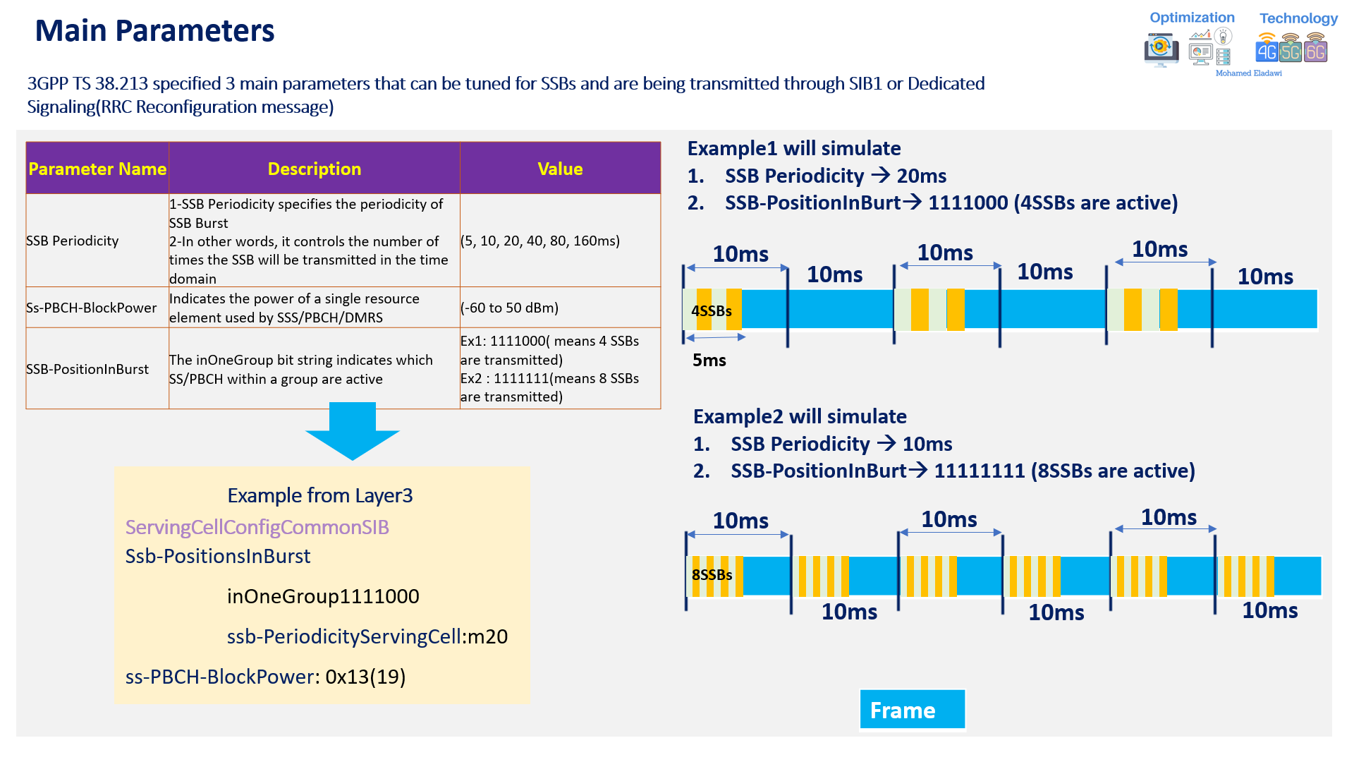
ssb-PeriodicityServingCell |
Controls how often the SSB burst is repeated in time | SIB1 / common serving-cell configuration | Typical values include 5, 10, 20, 40, 80, and 160 ms |
ss-PBCH-BlockPower |
Indicates the power of a single resource element used by SSS, PBCH, and related demodulation resources | SIB1 or dedicated signaling | Tuning this impacts SSB detectability and coverage footprint |
ssb-PositionsInBurst |
Indicates which candidate SS/PBCH blocks are active | SIB1 / common serving-cell configuration | Example: 1111000 means only part of the burst positions are active |
kSSB |
Defines the subcarrier offset from the common RB grid toward the SSB | MIB | Used together with OffsetToPointA in the relative positioning method |
OffsetToPointA |
Defines the RB offset between Common RB0 and the SSB-related position | SIB1 | Helps the UE locate the carrier bandwidth relative to the detected SSB |
AbsoluteFrequencySSB |
Gives the absolute SSB frequency position | RRC Reconfiguration / dedicated signaling | Common in NSA and mobility-related signaling |
AbsoluteFrequencyPointA |
Gives the absolute frequency of Point A / Common RB0 | RRC Reconfiguration / dedicated signaling | Used with AbsoluteFrequencySSB in the absolute positioning method |
A few practical examples:
ssb-PeriodicityServingCell = 20 msssb-PositionsInBurst = 1111000ss-PBCH-BlockPower = 19in an example Layer 3 representation
These parameters together control when, where, and how strongly SSB is transmitted.
Section 8
SSB overhead calculation
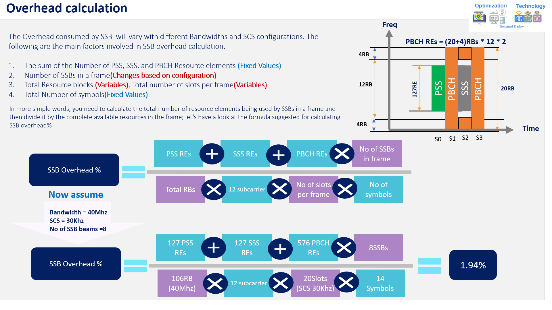
SSB does not come for free. It consumes time-frequency resources, and that consumption changes with the deployment configuration.
The overhead depends mainly on:
- the number of PSS resource elements
- the number of SSS resource elements
- the number of PBCH resource elements
- the number of SSBs transmitted in a frame
- the total carrier bandwidth in RBs
- the subcarrier spacing
- the number of slots per frame
- the number of symbols
A simple way to understand the calculation is this:
- calculate the total resource elements occupied by SSBs in one frame
- divide that by the total available resource elements in the frame
- convert the result to percentage
Main fixed values commonly used in the example
- PSS REs = 127
- SSS REs = 127
- PBCH REs = 576
Worked example
Assume:
- Bandwidth = 40 MHz
- SCS = 30 kHz
- Number of SSB beams = 8
- Total RBs = 106
- Slots per frame = 20
- Symbols per slot = 14
In this case, the resulting SSB overhead is about 1.94%.
What does this result tell us?
It tells us that increasing the number of SSB beams improves beam coverage and beam-based access flexibility, but it also increases overhead.
So, more beams are not always better. The design must balance:
- coverage
- access robustness
- beam granularity
- overhead cost
Section 9
Questions and Answers
Q1) Why is SSB so important during initial access?
Because it is the UE’s starting point for synchronization, physical cell ID acquisition, MIB decoding, and the next steps toward SIB1 and PRACH.
Q2) What is the difference between ARFCN and GSCN for SSB?
ARFCN is a direct frequency indication approach commonly associated with dedicated signaling, while GSCN defines allowed synchronization raster positions that make blind scan more efficient.
Q3) Why does the UE still need OffsetToPointA and kSSB after detecting the SSB?
Because detecting the SSB alone does not fully tell the UE where the carrier bandwidth is located relative to that SSB. The UE still needs the relative positioning information.
Q4) Why do we use multiple SSB beams instead of one wide beam?
Because multiple directional SSB beams improve beam-based initial access, increase coverage quality, and improve the chance that the UE finds a strong serving direction.
Q5) What is the downside of transmitting more SSB beams?
The main downside is higher overhead, because more time-frequency resources are occupied by SSB-related transmissions.
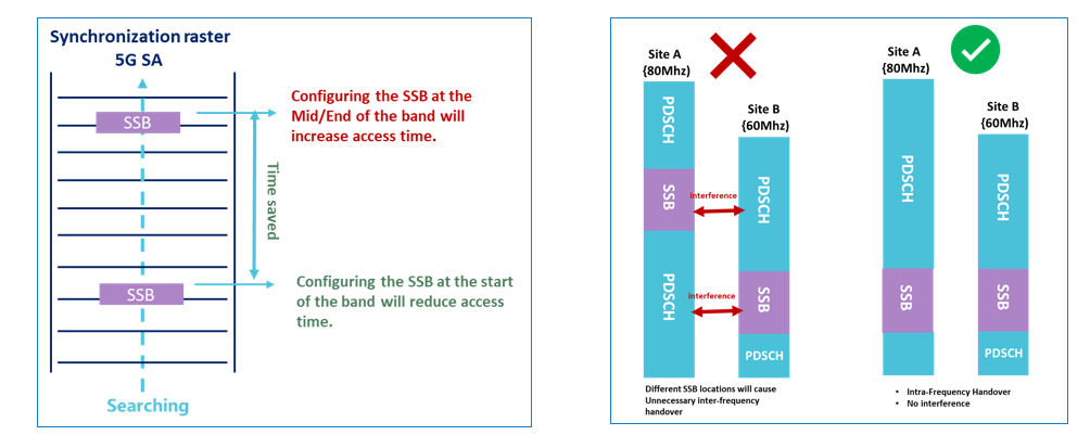
Q6) What main concerns and recommendations need to be considered when configuring the SSB Frequency position?
It`s recommended to configure the SSB frequency domain position at the bottom/start of the band, especially in 5G Standalone, to reduce the cell search time and, accordingly will, improve the access delay.
In case you have different Bandwidth configurations operating under the same frequency band. Configuring the SSB at the exact location for all sites. As this will reduce the unnecessary inter-frequency handovers and will also mitigate the interference caused by SSB <– --> PDSCH: Example: n78 operating with 80Mhz at Site A and with 60Mhz at Site B
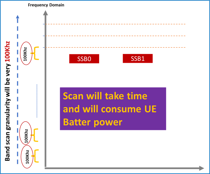
Q7) What are the differences between NSA & SA SSB Frequency domain position identification? And Why 5G SA is using only GSCN during SSB Scan?
In NSA, the UE will receive SSB frequency domain position through the RRC Reconfiguration message, which is very useful as it will make the UE find SSB Position very fast compared with 5G SA! Also, the power consumption will be less as the UE doesn’t need to scan the entire bandwidth to find SSB Position(Channel Raster-ARFCN uses low granularity (50, 60, and 100Khz).
In SA Mode, SSB Follows GSCN rasters; Raster means that there are some unique locations, and SSB follows some particular location every time, which means the UE Should scan these locations using certain granularity which differs from one band to another (1.2,1.44 & 17.4 MHz)
In 5G SA, it is not recommended for the UE to scan the band with the same granularity used in 5G NSA, as this will also increase the initial access time and power consumption.
Section 10
Summary and key takeaways
- SSB is the UE’s entry point into a 5G NR cell and is essential for synchronization, cell identification, broadcast decoding, and beam-based access.
- The UE first detects the SSB, then decodes PSS and SSS to obtain the physical cell ID, then decodes PBCH to obtain the MIB.
- SSB frequency location can be identified using ARFCN or GSCN, depending on the scenario.
- After detecting SSB, the UE still needs frequency-domain positioning information such as OffsetToPointA, kSSB, AbsoluteFrequencySSB, and AbsoluteFrequencyPointA.
- Time-domain SSB allocation depends on the applicable case, frequency range, and subcarrier spacing.
- SSB beam sweeping is a major 5G concept that improves directional access and beam selection, but it also introduces extra overhead.
- Key tuning parameters such as periodicity, beam positions, and block power have a direct impact on access behavior and coverage.
- A practical design goal is to balance detection speed, beam coverage, and overhead rather than maximizing one dimension alone.
Video for the same:
References
- 3GPP TS 38.211
- 3GPP TS 38.213
- 3GPP TS 38.331
- 5G NR in Bullets
Related articles
https://www.mohamedeladawi.com/ssb-position-plays-a-vital-role-in-5g/
https://www.mohamedeladawi.com/nr-ssb-calculation-materials/
https://www.mohamedeladawi.com/nr-ssb-calculation-explained/