5G HARQ Explained: Soft Combining, HARQ Processes, ACK/NACK Timing, Codebook Types, Spatial Bundling, and 4G vs 5G Differences (Article)


Introduction
- HARQ is one of the most important reliability mechanisms in the 5G MAC layer. It directly affects retransmission speed, uplink control overhead, latency, and overall scheduling efficiency.
- In simple words, HARQ gives 5G a fast retransmission loop. It helps recover transmission errors much faster than higher-layer recovery, which is why it plays a major role in user plane performance.
- This topic becomes especially important when you analyze throughput fluctuation, repeated retransmissions, uplink control signaling, or MAC/PHY behavior from traces.
Content
This article will cover:
- What HARQ is and why it matters
- The main functions of HARQ in 5G
- Detailed technical breakdown of 5G HARQ
- 3.1 HARQ typical pipeline
- 3.2 HARQ soft combining: Chase combining vs incremental redundancy
- 3.3 HARQ processes: Single vs multiple stop-and-wait
- 3.4 Code block group based HARQ retransmission
- 3.5 Flexible uplink HARQ ACK/NACK timing
- 3.6 HARQ-ACK multiplexing: Codebook types
- 3.7 Spatial bundling and its trade-offs
- Key HARQ parameters and where to find them
- How to verify HARQ in real logs and traces
- KPI and design impact of HARQ
- 4G vs 5G HARQ: Main differences
- Summary (Key takeaways)
(1) What HARQ is and why it matters
- HARQ stands for Hybrid Automatic Repeat reQuest. It is the fast retransmission mechanism used for downlink data on PDSCH and uplink data on PUSCH.
- Its main job is to detect transmission failures quickly and allow fast recovery through ACK/NACK feedback. This makes it much faster than relying only on higher-layer retransmission.
- It is called hybrid because it does not depend only on retransmission. It also combines error detection, error correction, buffering, and soft combining to improve decoding probability.
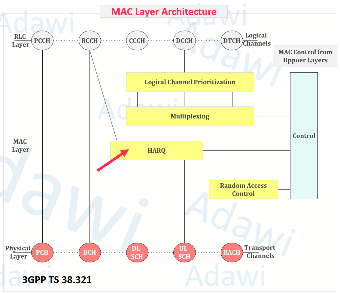
- At a high level, HARQ is part of the MAC layer behavior that sits between the RLC logical channels and the physical layer transport handling.
(2) The main functions of HARQ in 5G
The first function of HARQ is fast error recovery. If the receiver cannot decode the data correctly, it can return NACK quickly so the transmitter reacts without waiting for slower upper-layer procedures.
The second function is soft combining. Instead of discarding a failed transmission, the receiver stores it and combines it with the next retransmission to improve the chance of successful decoding.
The third function is latency reduction. HARQ gives a short retransmission loop, while RLC remains the backup mechanism when HARQ cannot fully recover the data.
This is why both HARQ and RLC are needed together:
- HARQ provides fast recovery and short reaction time
- RLC provides additional reliability if HARQ recovery is not enough
- Together, they improve both latency and reliability
(3) Detailed technical breakdown of 5G HARQ
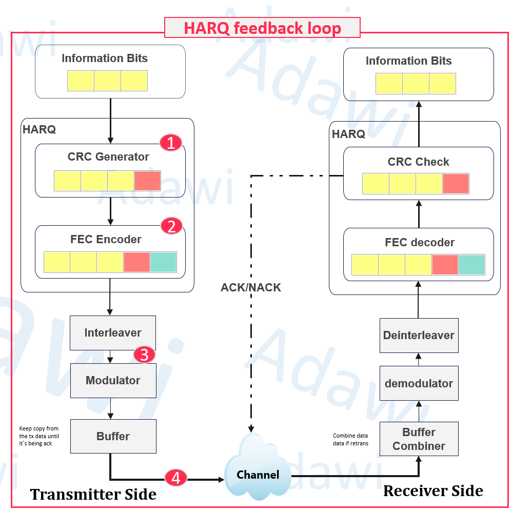
3.1 HARQ typical pipeline
A good way to understand HARQ is to follow the full transmitter and receiver loop.
- First, the information bits are prepared for transmission. Then CRC bits are added for error detection.
- After that, forward error correction (FEC) adds extra redundancy bits to help the receiver correct errors.
- Then the data goes through interleaving and modulation before transmission over the air.
- Then the symbols are sent over the wireless channel (H). During transmission, the signal gets affected by noise, interference, and fading.
The buffers on both sides are very important:
- the transmitter buffer keeps a copy of the transmitted data until ACK is received
- the receiver buffer keeps failed data so it can be combined with the next retransmission
This is one of the main differences compared to a simple retransmission model. HARQ does not just send the data again. It retransmits while still benefiting from what was already received.

3.2 HARQ soft combining: Chase combining vs incremental redundancy
Soft combining is one of the most important HARQ concepts.
If a transmission fails, the receiver does not simply discard the data. It stores the failed copy and combines it with the retransmission. This improves the decoding probability.
There are two main soft combining methods used here:
- Chase combining
- Incremental redundancy
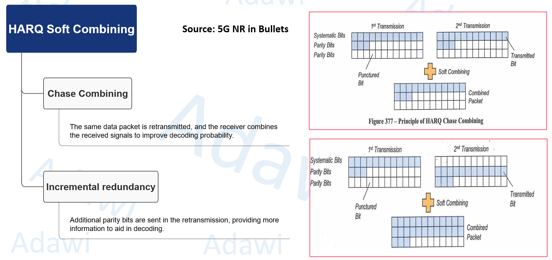
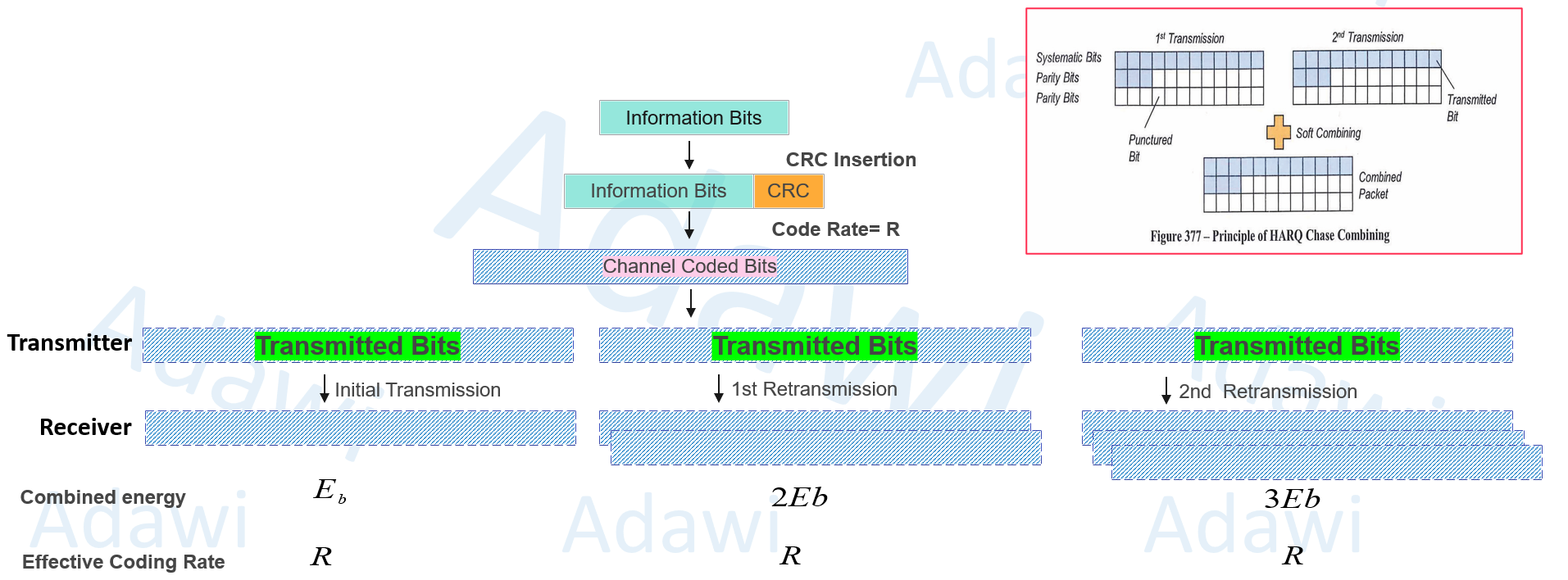
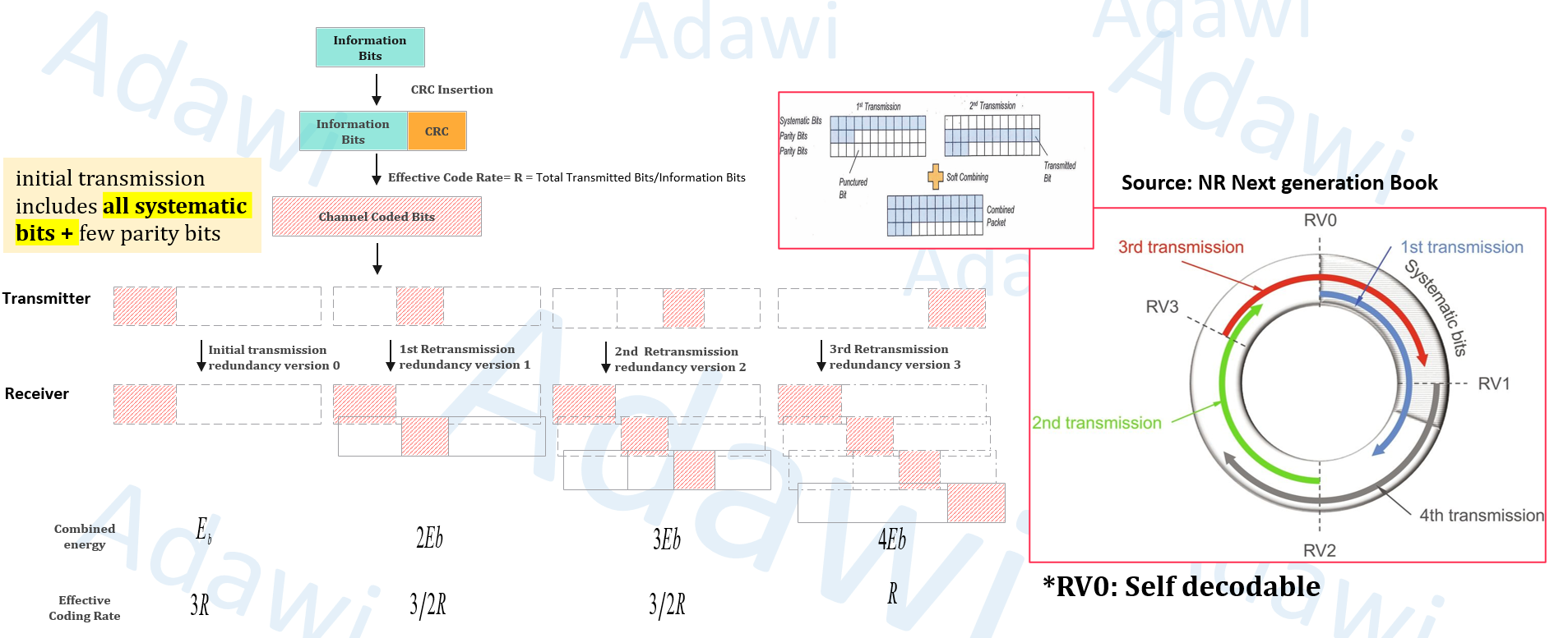
3.2.1 Chase combining
In Chase combining, the retransmission uses the same puncturing pattern as the original transmission.
This means the retransmitted packet carries the same physical-layer bit set as before. The receiver then combines the received copies, so the effective received energy increases with each retransmission.
Main points:
- same physical-layer bits are retransmitted
- combined energy increases
- effective coding rate stays the same
- simpler implementation
- lower UE memory requirement
3.2.2 Incremental redundancy
In incremental redundancy, the retransmission uses a different puncturing pattern from the original transmission.
Instead of sending the same bit set again, the retransmission provides different redundancy bits. This gives the receiver more useful information and improves the probability of successful decoding.
The first transmission typically includes all systematic bits and only part of the parity bits. If decoding fails, later retransmissions send additional redundancy versions.
Main points:
- retransmissions are not identical
- combined energy still increases
- effective coding rate becomes lower with more retransmissions
- decoding probability improves further
- complexity and UE memory requirement are higher
A very important point here is that RV0 is self-decodable, while the other redundancy versions mainly become useful when combined with the original transmission. (*RV0 = Redundancy Version 0)
This is also why incremental redundancy can be seen as a form of implicit link adaptation, because the retransmission itself improves decoding conditions by adding more useful redundancy.
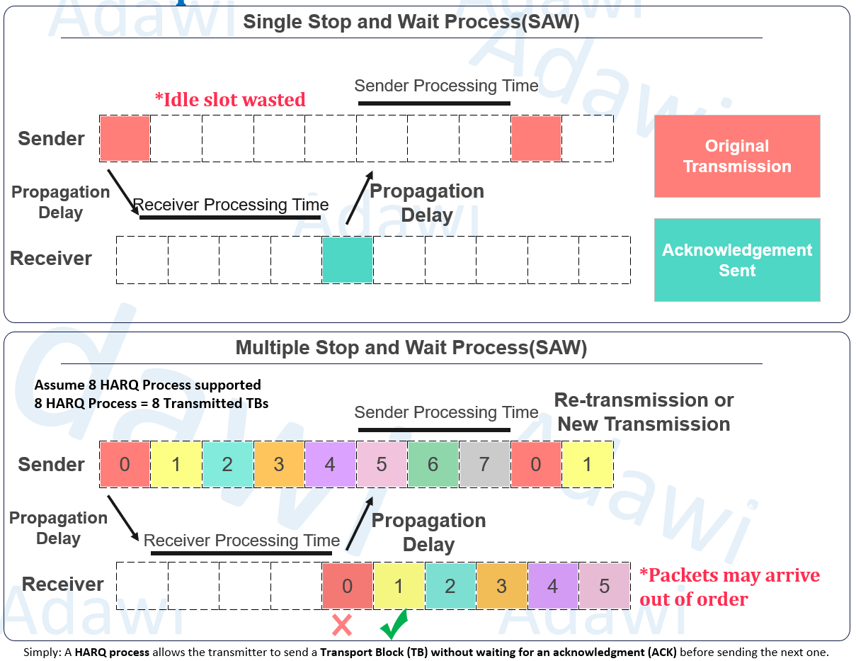
3.3 HARQ processes: Single vs multiple stop-and-wait
A HARQ process allows the transmitter to send a transport block without waiting for ACK before sending the next one.
In single stop-and-wait, the sender transmits one packet and then waits for ACK/NACK before sending the next packet. This creates idle time and wastes transmission opportunities.
In multiple stop-and-wait, the sender keeps sending multiple packets in parallel using different HARQ process IDs. This avoids idle time and improves efficiency.
Main points:
- single stop-and-wait introduces idle slots
- multiple stop-and-wait keeps the pipeline active
- retransmission of one packet does not block the others
- throughput improves and delay is reduced
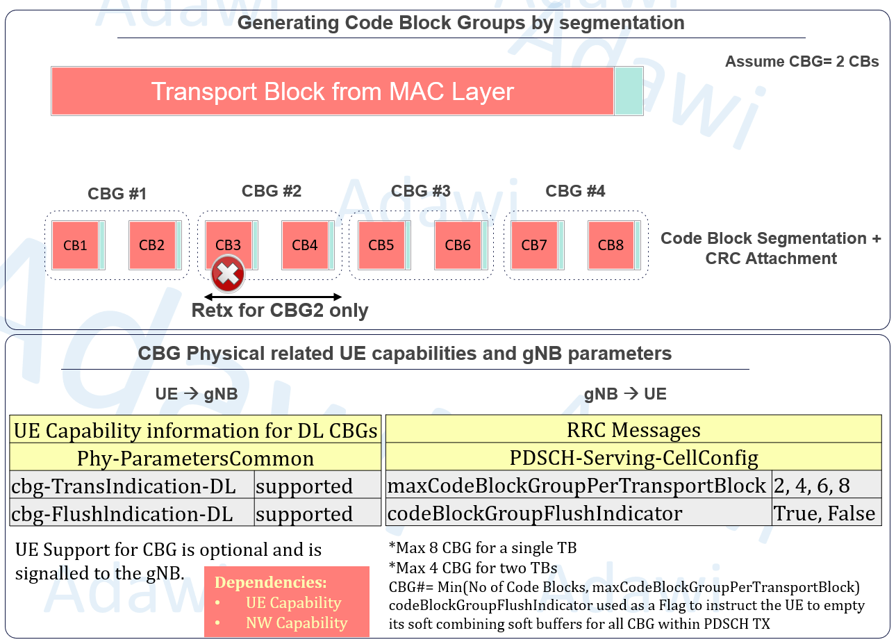
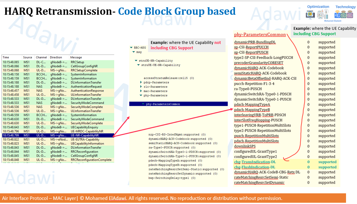
3.4 Code block group based HARQ retransmission
Large transport blocks are segmented after CRC attachment into smaller code blocks. This is done to keep decoding manageable and efficient.
If the whole transport block is retransmitted after a small error, resource usage becomes inefficient. On the other hand, retransmitting each individual code block would require too many ACK/NACK bits.
This is why code block group (CBG) based retransmission is useful. It creates a practical compromise:
- per transport block retransmission is simple but wasteful
- per code block retransmission is efficient but increases signaling overhead
- per code block group retransmission balances both sides
Important points:
- a transport block can be segmented into multiple code blocks
- multiple code blocks can be grouped into one CBG
- the network can retransmit only the failed CBG instead of the whole transport block
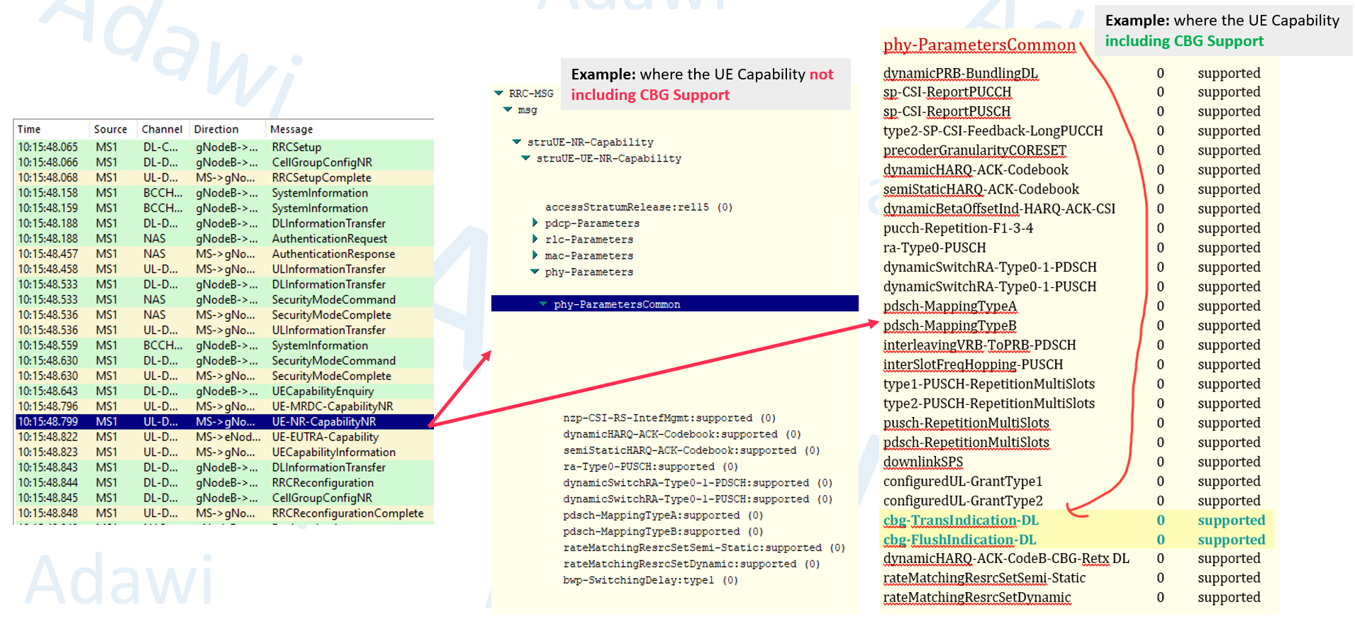
- UE support for CBG is optional and must be signaled to the gNB
Examples of related configuration and capability fields include:
cbg-TransIndication-DLcbg-FlushIndication-DLmaxCodeBlockGroupPerTransportBlockcodeBlockGroupFlushIndicator
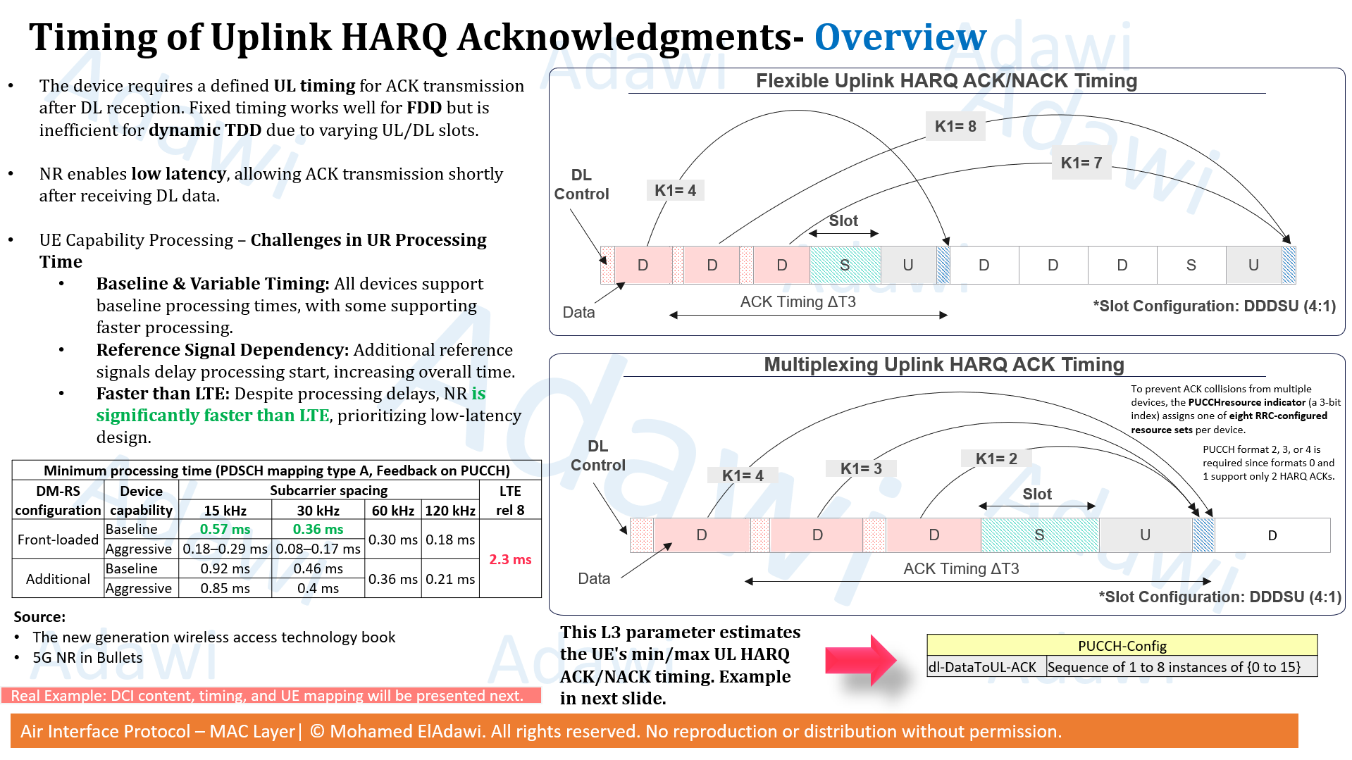
3.5 Flexible uplink HARQ ACK/NACK timing
One of the key 5G HARQ improvements is that ACK/NACK timing is flexible.
In 4G, HARQ timing was more fixed. In 5G, the feedback timing can be configured by the network, which is especially important in TDD deployments.
Flexible HARQ ACK/NACK timing is one of the most important 5G HARQ improvements because it directly affects latency, retransmission speed, and scheduler flexibility.
So the UE does not always send the ACK/NACK after one fixed delay. Instead, it uses the configured mapping and the DCI indication to determine the correct timing.
In simple words, after the UE receives downlink data on the PDSCH, it does not always send the HARQ ACK/NACK after one fixed delay. Instead, the network can configure multiple possible timing offsets, and the UE selects the correct one based on the DCI field received for that scheduled PDSCH. This flexibility is controlled through:
dl-DataToUL-ACKin RRC signaling- A timing indicator field in DCI
This is very useful in 5G, especially in TDD systems, because uplink and downlink slot locations are not always fixed in the same way as in simpler timing models. A fixed ACK timing may work well in FDD, but it becomes less efficient in dynamic TDD because the available UL opportunities may vary from one slot pattern to another. 5G solves this by making the uplink HARQ feedback timing more flexible.
3.5.1 Theoretical deep understanding
At a high level, the UE needs enough time to do three things before sending the ACK/NACK:
- receive and decode the downlink control and data
- process the PDSCH and determine whether decoding was successful
- prepare and transmit the HARQ feedback on the uplink
This is why HARQ timing cannot be random. The network must select a timing value that is large enough for UE processing, but still small enough to keep latency low.
The main timing value used here is usually K1.
- K1 represents the slot offset between the downlink PDSCH reception and the uplink HARQ ACK/NACK transmission
- in most practical cases, the ACK/NACK is returned on PUCCH using this K1 timing
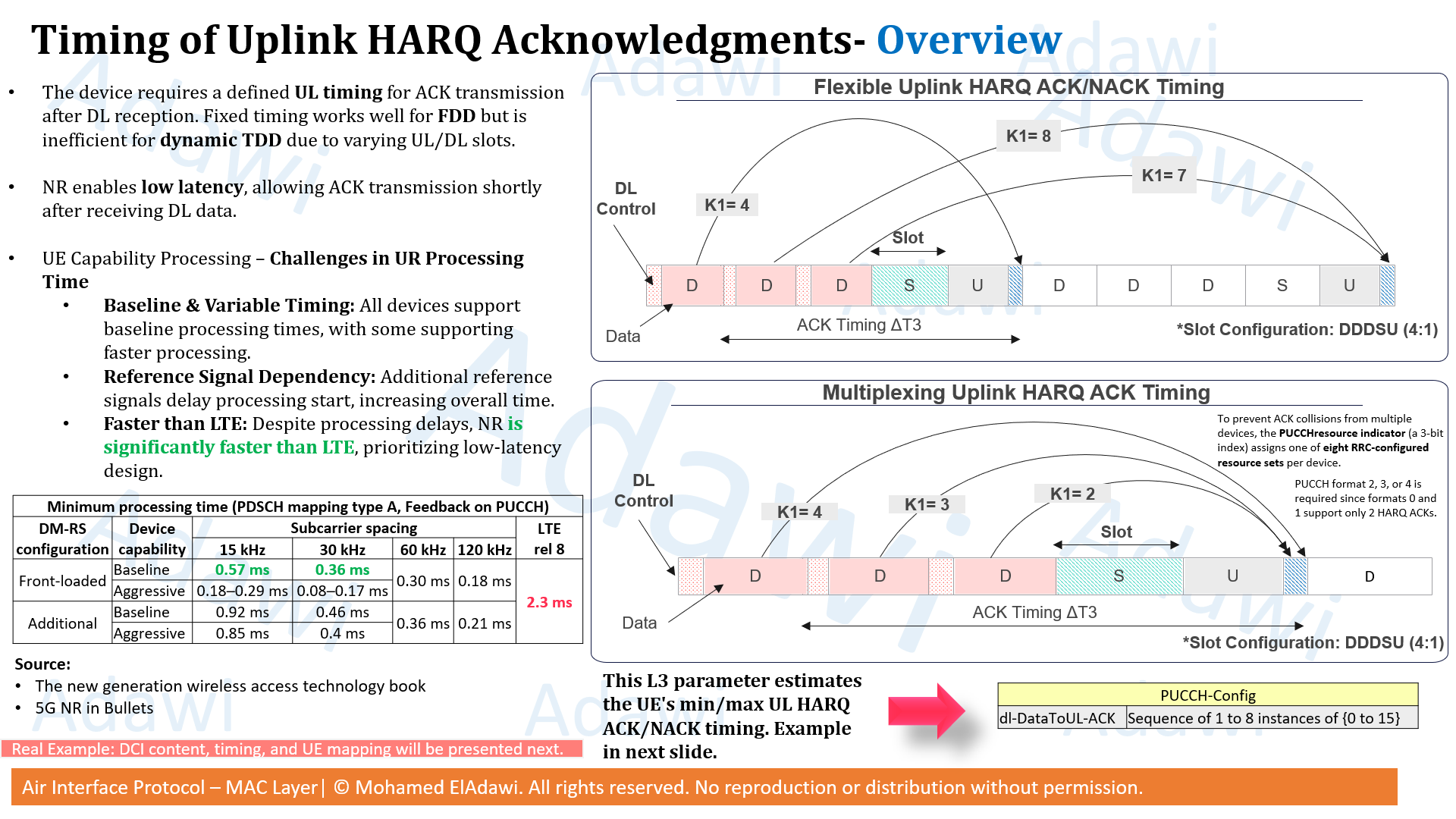
- in some cases, the HARQ ACK can also be returned on PUSCH, which is controlled through K2
The timing is configured through an RRC parameter under PUCCH-Config called:
dl-DataToUL-ACK
This parameter provides a sequence of possible timing values. The network is basically telling the UE: for downlink HARQ feedback, these are the allowed slot offsets you may use.
Then, when the gNB schedules a specific PDSCH, it sends a DCI field called:
PDSCH-to-HARQ Feedback Timing Indicator
This field does not directly give the final number of slots. Instead, it acts as an index selector. The UE uses it to choose one value from the configured dl-DataToUL-ACK list.
The mapping logic is:
000→ use the 1st value fromdl-DataToUL-ACK001→ use the 2nd value010→ use the 3rd value011→ use the 4th value100→ use the 5th value101→ use the 6th value110→ use the 7th value111→ use the 8th value
So the full HARQ timing decision comes from two layers together:
- the RRC layer provides the list of allowed timing candidates
- the DCI tells the UE which candidate to use for that specific scheduled PDSCH
Another very important point is UE processing time. Even if the scheduler wants a very short ACK timing, the UE still needs enough time to process the downlink data first. This is why the selected K1 must be consistent with UE capability, DM-RS configuration, and numerology.
The processing capability values shown for PDSCH mapping type A with feedback on PUCCH highlight how much faster 5G can be compared with LTE. Example values shown are around:
- 0.57 ms at 15 kHz
- 0.36 ms at 30 kHz
- 0.30 ms at 60 kHz
- 0.18 ms at 120 kHz
So from a design point of view, flexible HARQ timing is doing three things at once:
- adapting to the UL/DL slot structure
- respecting UE processing capability
- minimizing feedback delay to keep the HARQ loop fast
3.5.2 How the UE decodes the practical information from field logs
Now let us move from theory to the real trace example.
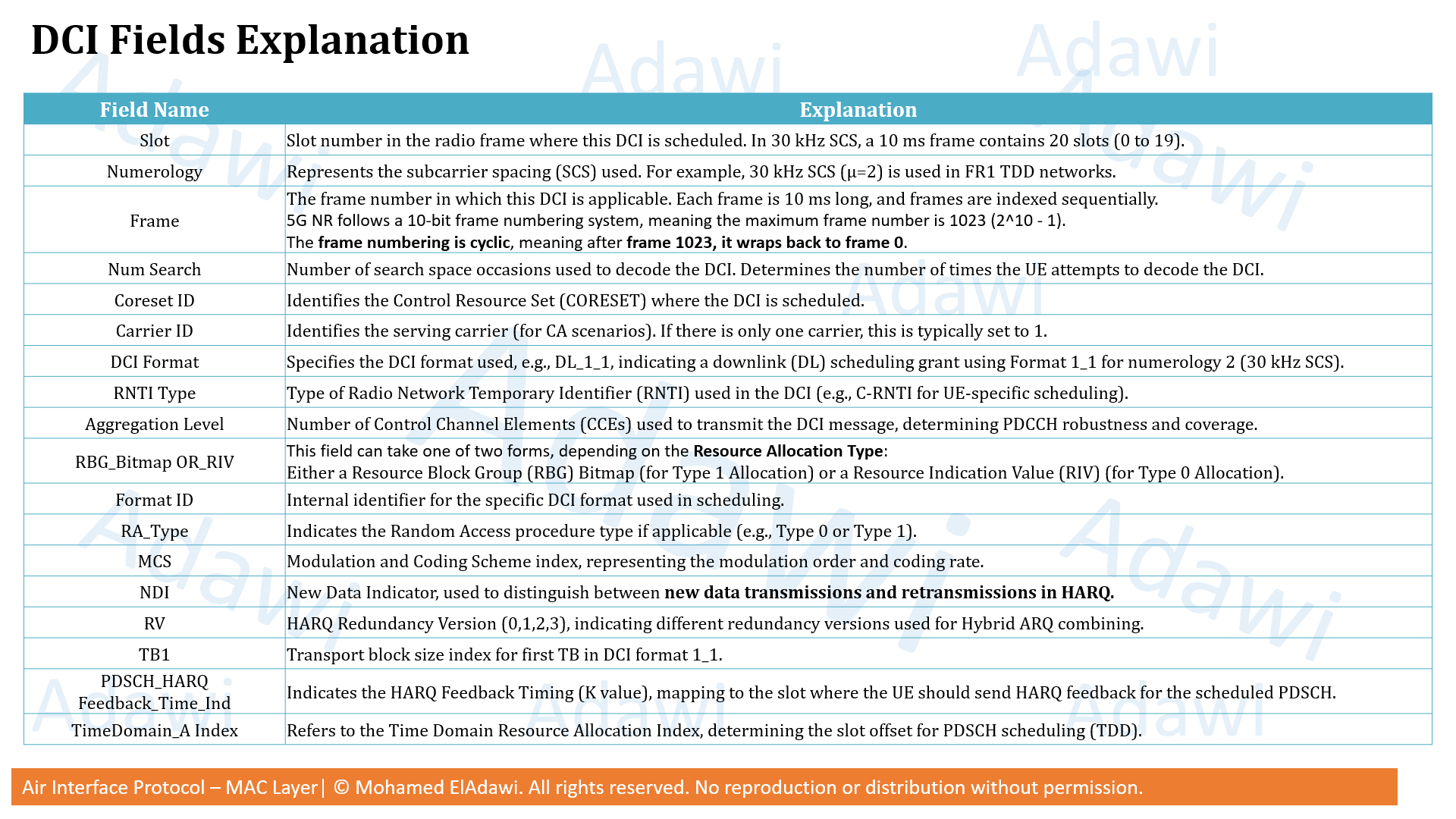
The shown trace is for DCI Format DL_1_1 with 30 kHz numerology, and the RRC setup indicates a 5G SA TDD UL/DL pattern of (8:2). The DCI contains many fields, but for HARQ ACK timing the most important ones are:
- Slot
- Numerology
- HARQ Process
- NDI
- RV
- PDSCH_HARQ_Feedback_Time_Ind
The practical UE logic is:
Step 1: read the slot where the PDSCH was scheduled.
Step 2: read the PDSCH_HARQ_Feedback_Time_Ind field in the DCI.
Step 3: map that field to the corresponding entry number using the 3GPP table.
Step 4: go to the RRC-configured dl-DataToUL-ACK list and pick that entry.
Step 5: the selected entry gives the actual K1 value in slots.
Step 6: count K1 slots forward from the PDSCH slot to know where the UE should send the ACK/NACK.
Step 7: convert the slot offset to time using numerology. In this example, with 30 kHz SCS, 1 slot = 0.5 ms.
Using the trace example:
| PDSCH Slot | PDSCH_HARQ_Feedback_Time_Ind |
Mapping result | Selected K1 | Feedback delay |
|---|---|---|---|---|
| 4 | 000 |
1st configured value | 4 | 2 ms |
| 5 | 110 |
7th configured value | 12 | 6 ms |
| 12 | 010 |
3rd configured value | 6 | 3 ms |
| 14 | 001 |
2nd configured value | 5 | 2.5 ms |
This means the UE behavior in the trace is as follows:
- For the PDSCH scheduled in slot 4, the feedback indicator is
000. The UE maps this to the 1st value indl-DataToUL-ACK, which is 4, so the ACK/NACK is sent after 4 slots, equal to 2 ms. - For the PDSCH scheduled in slot 5, the indicator is
110. The UE maps this to the 7th value, which is 12, so the feedback is sent after 12 slots, equal to 6 ms. - For the PDSCH scheduled in slot 12, the indicator is
010. The UE maps this to the 3rd value, which is 6, so the feedback is sent after 6 slots, equal to 3 ms. - For the PDSCH scheduled in slot 14, the indicator is
001. The UE maps this to the 2nd value, which is 5, so the feedback is sent after 5 slots, equal to 2.5 ms.
So the key practical conclusion from this trace is that the HARQ feedback delay is not fixed even inside the same configuration. In the shown example, the UE may return feedback anywhere between 2 ms and 6 ms, depending on the DCI-selected K1 value.
This is very important when estimating:
- HARQ round-trip timing
- retransmission delay
- scheduler responsiveness
- latency behavior in TDD systems
Also note that the ACK/NACK is commonly returned on PUCCH, but it can also be returned using PUSCH (K2) in some cases. So if you are troubleshooting a specific vendor log, do not assume PUCCH blindly without checking the actual configuration.
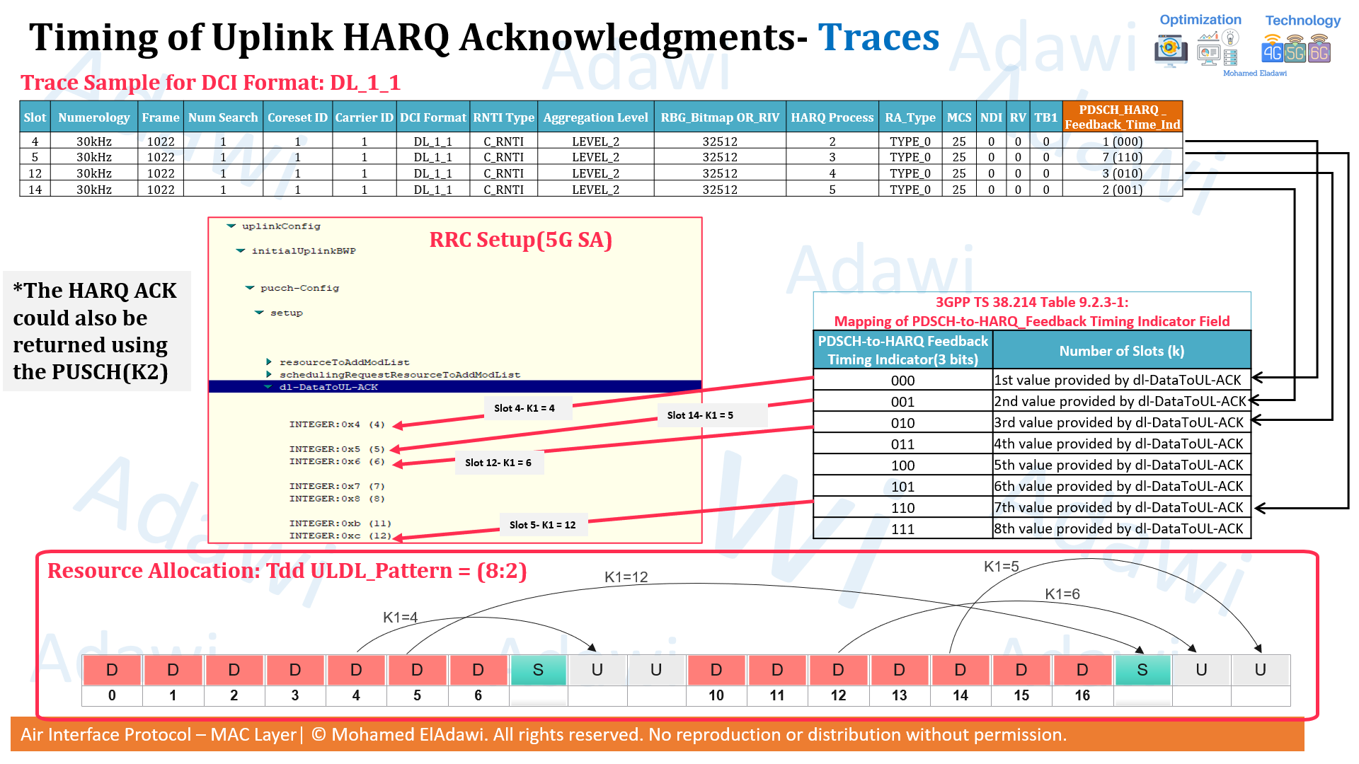
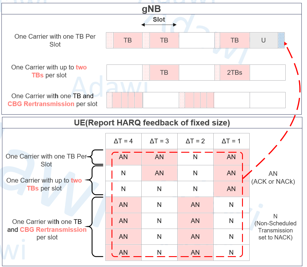
3.6 HARQ-ACK multiplexing: Codebook types
The HARQ-ACK codebook defines how ACK/NACK feedback is reported from the UE to the gNB.
This codebook allows feedback multiplexing across:
- multiple transport blocks
- multiple carriers
- multiple code block groups
The main codebook types highlighted here are:
- Type 1: Semi-static
- Type 2: Dynamic
- Type 3: Release 16
3.6.1 Type 1: Semi-static codebook
In the semi-static codebook, the HARQ-ACK feedback structure is fixed.
This means the UE sends feedback in a fixed-size format, even if no data was received in some positions. That makes the feedback more predictable and easier for the network to track.
Advantages:
- predictable and robust
- easy for the gNB to map feedback to transmissions
- supports multiple transmission configurations
Drawbacks:
- higher overhead
- includes unused ACK/NACK positions
- less flexible
So the semi-static codebook gives better alignment and predictability, but it consumes more uplink resources.
3.6.2 Type 2: Dynamic codebook
In the dynamic codebook, HARQ-ACK feedback is generated only for actual received downlink transmissions.
If no transmission was received, no HARQ-ACK bit is allocated for it. This saves uplink resources and makes the feedback more efficient.
To keep the transmission-to-feedback relationship correct, the UE uses:
- cDAI = counter Downlink Assignment Index
- tDAI = total Downlink Assignment Index
These counters help the UE detect gaps and identify where NACK information is needed if a transmission was missed.
Advantages:
- lower overhead
- more efficient use of uplink resources
- better for adaptive and varying traffic patterns
Drawbacks:
- more complex mapping
- more dependence on correct tracking of assignments
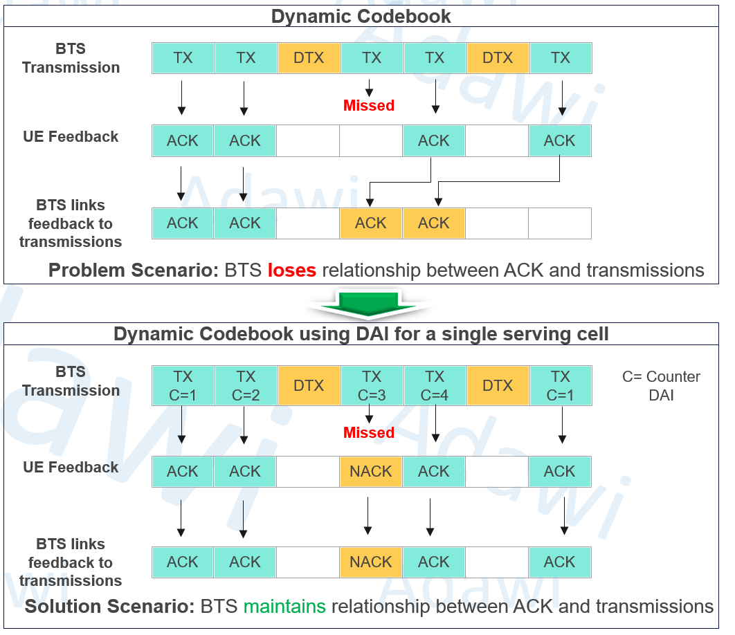
cDAI tells the UE: “You are now at item number X in the sequence of downlink assignments. So it behaves like a running counter or position number. It helps the UE know where this current scheduling message sits among the DL assignments that belong to the same HARQ-ACK reporting window. 3GPP-based wording describes cDAI as an accumulative number up to the current point. Simple Analogy: cDAI is like writing on each paper: This is paper 2”, “This is paper 3”, “This is paper 4.
tDAI tells the UE: “The total number of downlink assignments you should expect in this group is Y. So it behaves like the final total. It helps the UE know how many DL assignments in total must be considered when building the HARQ-ACK feedback. 3GPP-related sources describe tDAI as the total number up to the current monitoring occasion, and practical explanations describe it as the total DL transmissions to be reported in one UL HARQ-ACK report. Simple Analogy: tDAI is like telling the UE: “In total, there should be 4 papers.
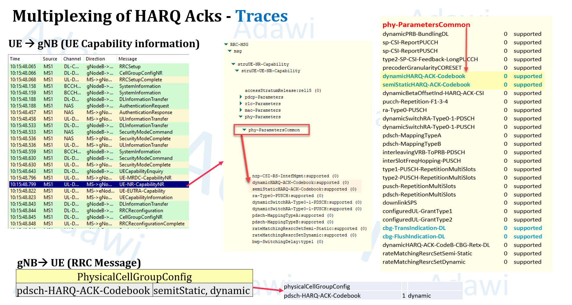
3.6.3 HARQ-ACK codebook traces
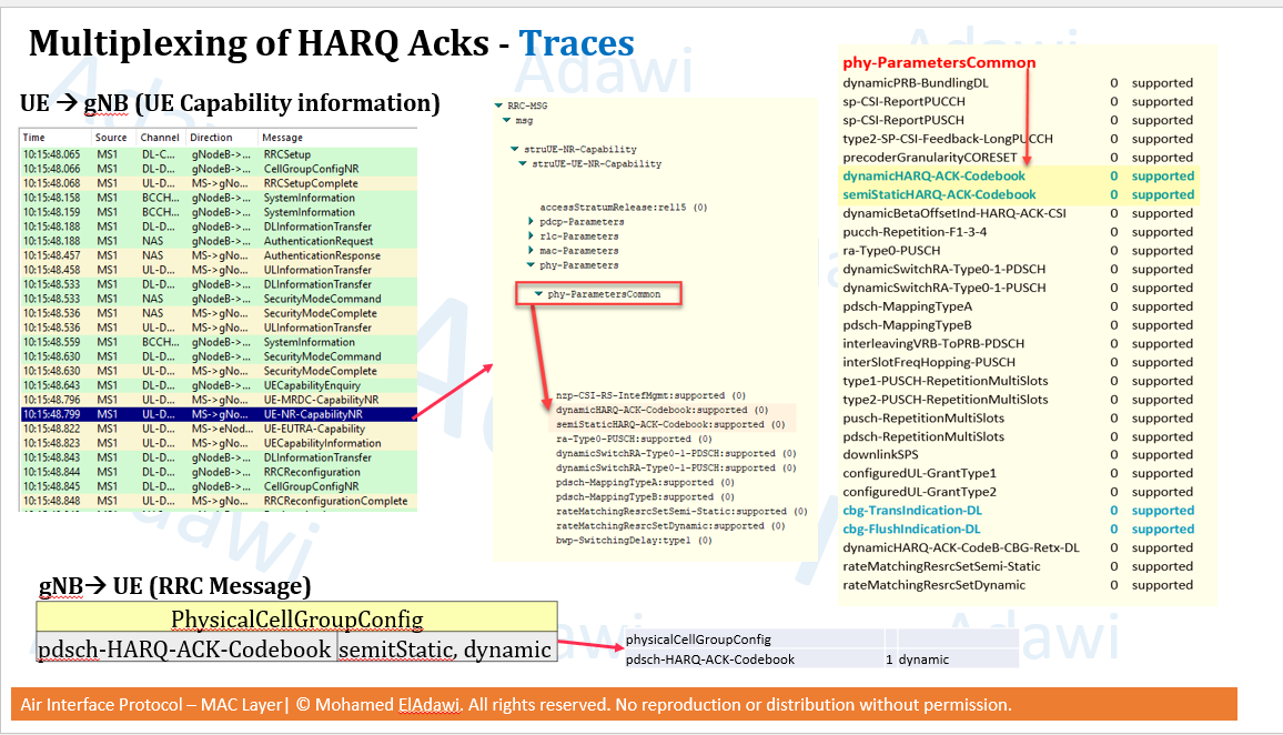
In traces, the HARQ-ACK codebook behavior can be checked through UE capability and RRC configuration.
Useful fields include:
pdsch-HARQ-ACK-CodebookphysicalCellGroupConfig
These help confirm whether the UE and network are using semi-static or dynamic HARQ-ACK feedback.
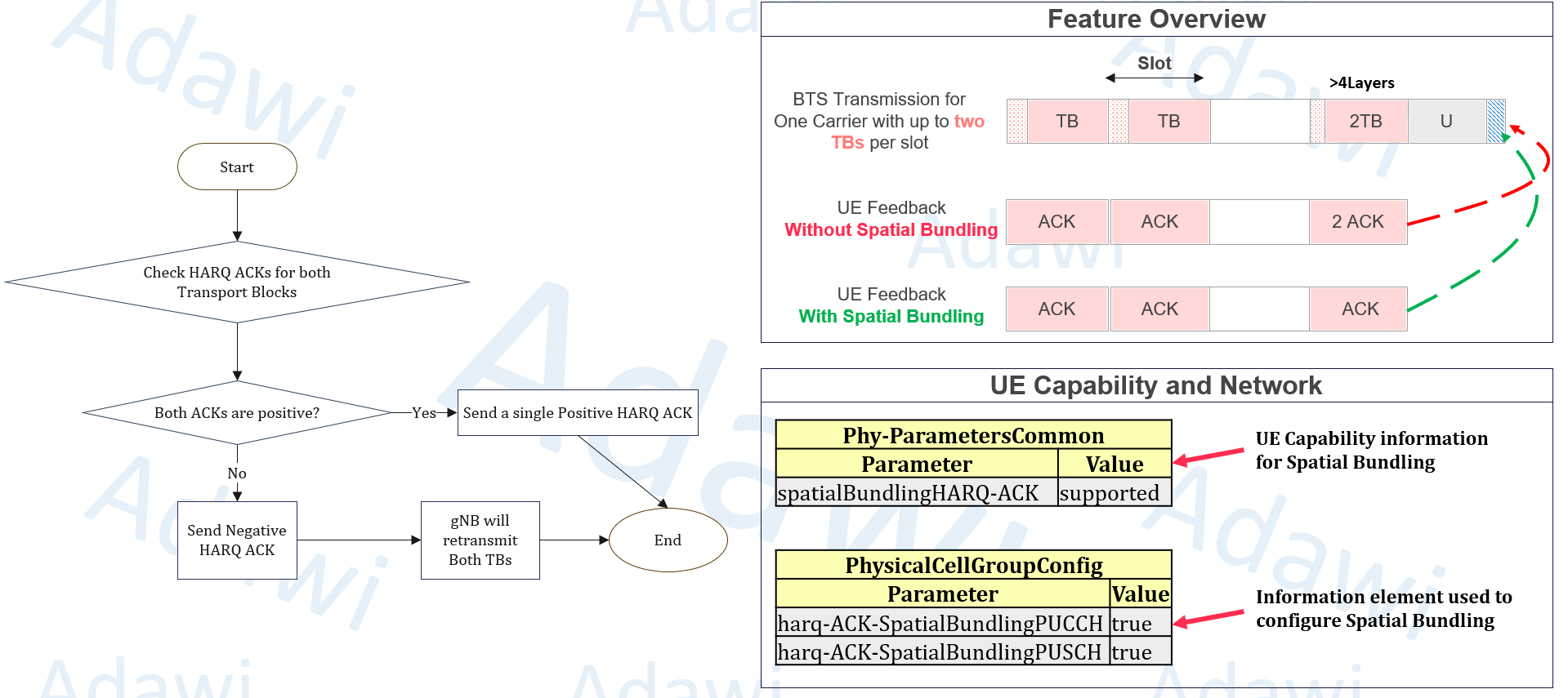
3.7 Spatial bundling and its trade-offs
Spatial bundling is another useful HARQ-related feature.
When the UE receives two transport blocks from a single cell, it does not have to send separate HARQ ACKs for both of them. Instead, it can send one bundled HARQ ACK for the pair.
Benefits:
- reduces HARQ ACK signaling overhead
- improves PUCCH capacity
- useful in scenarios with strong radio conditions
Potential drawback:
- if one transport block fails, the UE sends negative feedback
- the gNB may retransmit both transport blocks
- this can increase retransmitted data volume
So spatial bundling is helpful when radio conditions are strong and the risk of repeated decoding failures is low.
Related capability and configuration fields include:
spatialBundlingHARQ-ACKharq-ACK-SpatialBundlingPUCCHharq-ACK-SpatialBundlingPUSCH
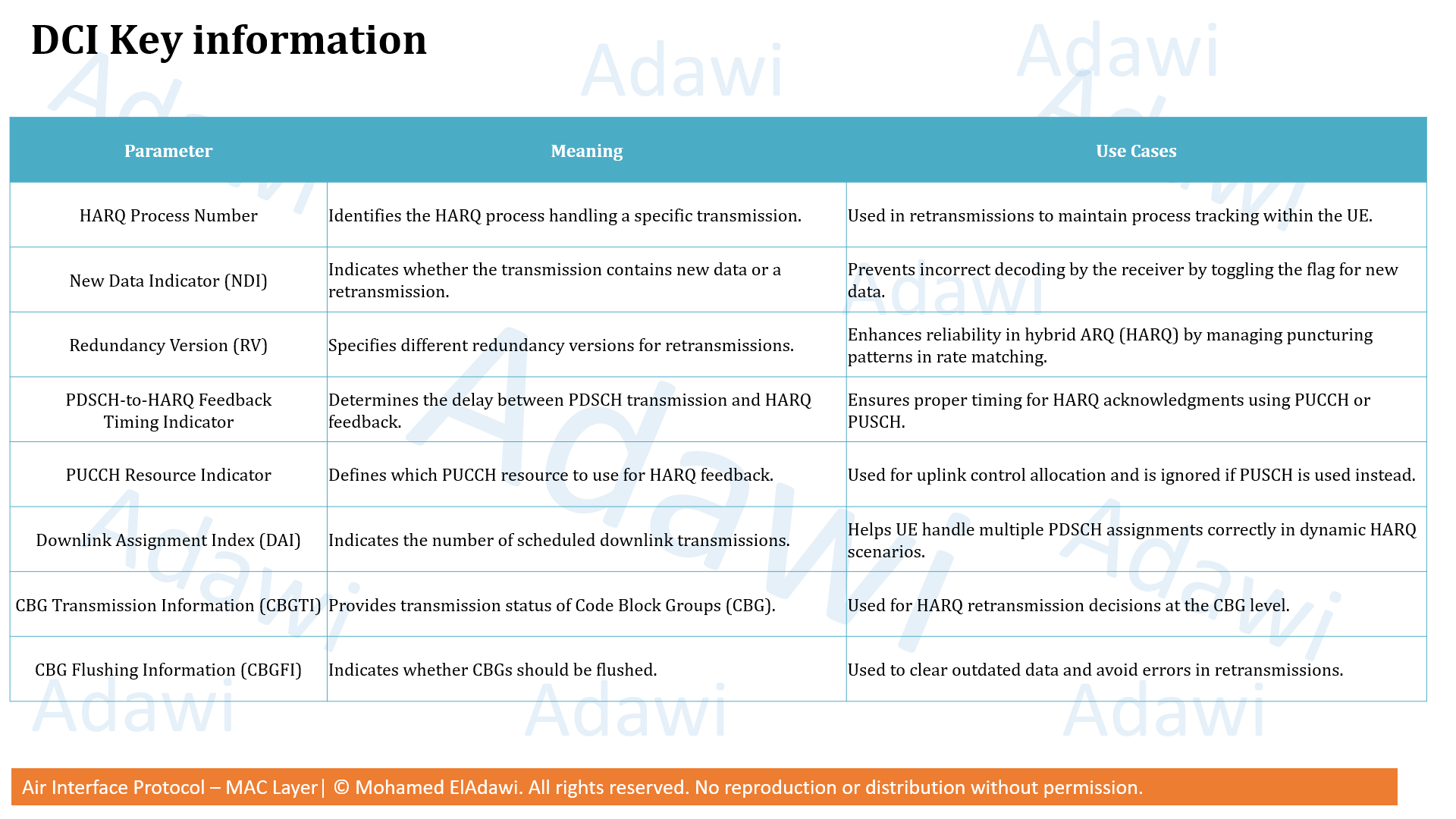
(4) Key HARQ parameters and where to find them
| Parameter | What it controls | Where it appears | Practical note |
|---|---|---|---|
| HARQ Process Number | Identifies the HARQ process handling a transmission | DCI / traces | Very important to track new transmission vs retransmission |
| NDI | Distinguishes new data from retransmission | DCI / traces | Toggling usually indicates new data for that HARQ process |
| RV | Identifies the redundancy version used | DCI / traces | Critical for understanding incremental redundancy behavior |
| PDSCH-to-HARQ Feedback Timing Indicator | Selects the HARQ feedback timing offset | DCI / traces | Must be mapped to dl-DataToUL-ACK |
| PUCCH Resource Indicator | Selects which PUCCH resource is used for feedback | DCI / traces | Important when multiple HARQ ACKs are multiplexed |
| DAI | Helps align feedback with downlink assignments | DCI / traces | Important especially for dynamic codebook behavior |
| CBGTI | Indicates code block group transmission information | DCI / traces | Used in CBG-based retransmission decisions |
| CBGFI | Indicates whether CBG buffers should be flushed | DCI / traces | Helps avoid combining outdated CBG information |
dl-DataToUL-ACK |
Provides the configured list of possible HARQ feedback delays | RRC messages | The DCI timing field points to one of these values |
pdsch-HARQ-ACK-Codebook |
Indicates the configured HARQ-ACK codebook type | UE capability / RRC messages | Used to confirm semi-static or dynamic feedback mode |
spatialBundlingHARQ-ACK |
Indicates support for spatial bundling | UE capability | Must be supported before enabling bundling |
(5) How to verify HARQ in real logs and traces
When checking HARQ behavior in logs, start from three main areas: UE capability, RRC configuration, and DCI/Layer 2 traces.
Where to check in UE capability and RRC
Look for:
cbg-TransIndication-DLcbg-FlushIndication-DLpdsch-HARQ-ACK-CodebookspatialBundlingHARQ-ACKdl-DataToUL-ACK
These confirm whether the UE supports the intended HARQ features and whether the network configured them.
What to check in DCI and Layer 2 traces
Focus on:
- HARQ Process Number
- NDI
- RV
- PDSCH-to-HARQ Feedback Timing Indicator
- PUCCH Resource Indicator
- DAI
- CBGTI
- CBGFI
These fields help you understand:
- whether it is a new transmission or retransmission
- which HARQ process is being used
- which redundancy version is being applied
- when the ACK/NACK is expected
- whether CBG-based retransmission is active
(6) KPI and design impact of HARQ
HARQ has a direct impact on several important network behaviors.
Throughput
Multiple HARQ processes keep the transmission pipeline active. This avoids idle time and improves throughput.
Latency
Flexible HARQ timing and faster UE processing help reduce retransmission delay. This is one of the reasons why 5G can react faster than 4G.
Uplink control overhead
HARQ feedback consumes uplink resources. Semi-static codebooks, multiple transport blocks, and CBG-based reporting can increase this overhead. Dynamic codebooks and spatial bundling can reduce it in the right scenarios.
Retransmission efficiency
Chase combining improves decode probability by increasing combined energy. Incremental redundancy improves it further by adding more useful parity information. CBG-based retransmission avoids resending the whole transport block when only part of it failed.
Complexity and UE memory
Advanced HARQ features improve efficiency, but they also increase complexity and memory requirements at the UE side.
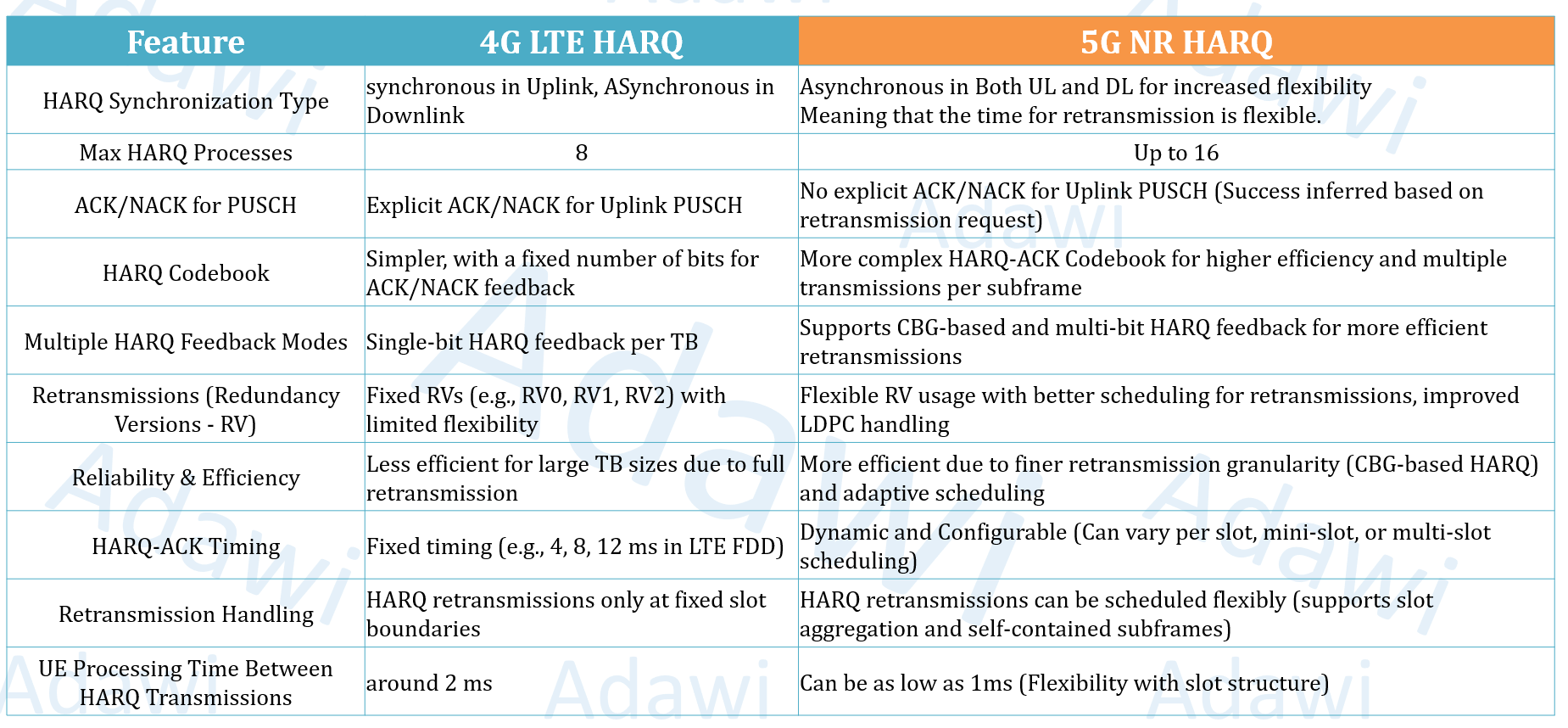
(7) 4G vs 5G HARQ: Main differences
| Feature | 4G LTE HARQ | 5G NR HARQ |
|---|---|---|
| HARQ synchronization type | Synchronous in UL, asynchronous in DL | Asynchronous in both UL and DL |
| Maximum HARQ processes | 8 | Up to 16 |
| ACK/NACK for PUSCH | Explicit ACK/NACK for uplink PUSCH | No explicit ACK/NACK for uplink PUSCH |
| HARQ codebook | Simpler and more fixed | More advanced and more flexible |
| HARQ feedback modes | Single-bit HARQ feedback per TB | Supports CBG-based and multi-bit feedback |
| Redundancy handling | More limited flexibility | Better scheduling flexibility with improved redundancy handling |
| Retransmission granularity | Less efficient for large TBs | More efficient with finer granularity such as CBG-based retransmission |
| HARQ timing | More fixed | Dynamic and configurable |
| Retransmission handling | Fixed retransmission timing boundaries | More flexible slot-based retransmission behavior |
| UE processing time | Around 2 ms | Can be as low as 1 ms |
(8) Summary (Key takeaways)
- HARQ is the fast retransmission loop of 5G MAC behavior.
- It improves reliability through error detection, error correction, buffering, and soft combining.
- Chase combining retransmits the same bits, while incremental redundancy retransmits different redundancy versions.
- Multiple HARQ processes improve throughput by avoiding idle wait time.
- CBG-based retransmission improves efficiency by avoiding full transport block retransmission.
- Flexible HARQ timing is one of the major 5G improvements compared to 4G.
- Semi-static and dynamic codebooks trade robustness against overhead efficiency.
- Spatial bundling can reduce uplink control overhead, but it may increase retransmitted data in some cases.
- 5G HARQ is more flexible, more scalable, and more efficient than 4G HARQ.
References
- 3GPP TS 38.321
- 3GPP TS 38.214
- 5G NR in Bullets
- The New Generation Wireless Access Technology Book