SRS-Based Beamforming in 5G | PDSCH & PDCCH, Antenna Switching, SRS Gain Explained (Article)

Introduction
SRS-based beamforming is one of the most important topics to understand after learning the basics of 5G beamforming, SSB, CSI-RS, and codebook-based operation.
In practical terms, this topic explains how the gNB can use uplink SRS sounding to estimate the downlink propagation channel and then generate better PDSCH beams. It also explains where this method helps, where it becomes limited, and why antenna switching and UE capability matter.
This topic is also highly relevant when you analyze TDD beamforming behavior, cell-edge throughput, uplink coverage limits, SRS configuration, and real Layer 3 signaling.
Content
This article will cover:
- What SRS-based beamforming is and why it matters
- The main functions of SRS in this context
- Detailed technical breakdown
- Key SRS-related parameters and where to find them
- Practical example: 2T4R UE with antenna switching
- How to verify in real logs and traces
- Summary (Key takeaways)
1. What SRS-based beamforming is and why it matters
SRS-based beamforming means the gNB uses uplink Sounding Reference Signal measurements to estimate the channel and derive the downlink precoding needed for traffic transmission.
In this session, the main focus is on using SRS for PDSCH beamforming in TDD systems through channel reciprocity. In simple words, the uplink sounding helps the gNB understand how to shape the downlink traffic beam toward the UE.
This matters because it reduces dependence on explicit downlink PMI feedback all the time, and it can give the network a faster and more direct way to build traffic beams when the conditions are suitable.
2. The main functions of SRS in this context
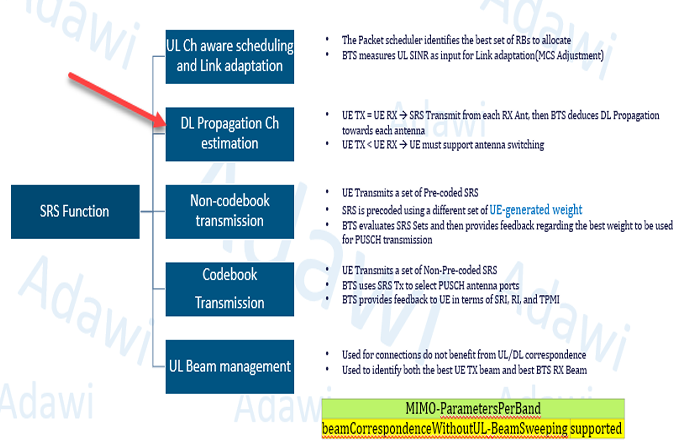
Before focusing on downlink beamforming, it is important to remember that SRS has more than one role in NR.
The first role is uplink channel-aware scheduling and link adaptation. The gNB can measure the uplink channel quality from SRS, estimate SINR, and use that to support RB allocation and MCS selection.
The second role, which is the key focus of this article, is downlink propagation channel estimation. In TDD, the gNB can use SRS measurements to estimate the downlink channel and then calculate the precoding matrix for PDSCH transmission.
The third point is that SRS also sits inside the wider beam-management framework. In this session, however, the main attention is on downlink traffic beamforming, antenna switching, and the related optimization trade-offs.
3. Detailed technical breakdown
3.1 How PDSCH beamforming using SRS works
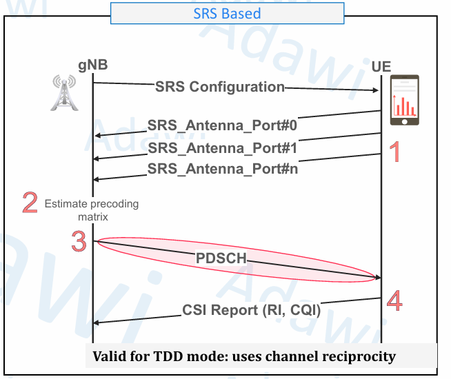
At a high level, the SRS-based PDSCH beamforming flow is straightforward.
- The gNB first sends the SRS configuration to the UE through RRC Reconfiguration.
- The UE then transmits SRS according to the configured resource set, resource type, symbols, and bandwidth configuration.
- The gNB measures the SRS and estimates the downlink propagation channel through channel reciprocity.
- Based on that estimate, the gNB calculates the precoding matrix.
- The gNB then transmits the PDSCH using the calculated precoder.
- After that, the UE can still report information such as RI and CQI, which can help further tuning.
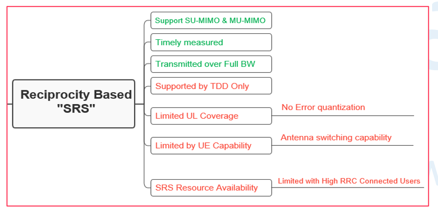
A very important point here is that this method is mainly tied to TDD operation, because the gNB depends on uplink and downlink channel reciprocity.
Another very important point is that SRS does not directly quantify downlink interference conditions. This means the beam estimate may still need refinement using CSI-related feedback, especially when interference becomes important.
3.2 Why UE antenna switching is needed
The idea of antenna switching becomes important when the UE has fewer transmit paths than receive paths.
If the UE has equal TX and RX paths, such as 1T1R, 2T2R, or 4T4R, the situation is simpler. Each transmit path can already represent the required receive-side sounding view, so special antenna switching support is not needed.
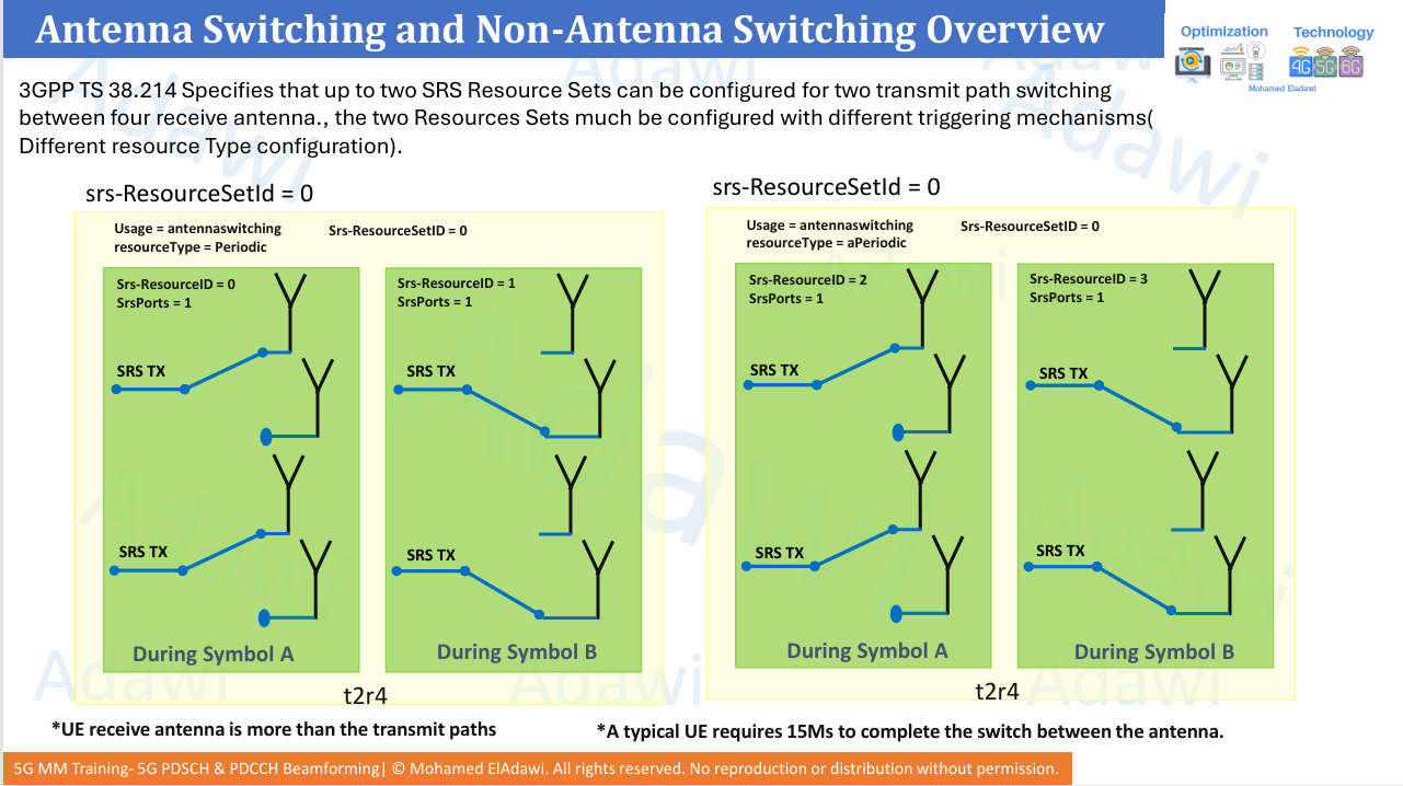
The harder case is when the UE has something like 2T4R. Here, the gNB needs knowledge about all four UE receive branches for accurate downlink beamforming, but the UE can only sound using two transmit paths at a time.
That is why the UE must support antenna switching. It switches the SRS transmit path across different receive-antenna pairs over different SRS occasions, so the gNB can eventually learn the radio condition seen by all receive branches.
In simple words, antenna switching is the UE’s way to expose the full receive-side channel view to the gNB, even though the UE has fewer transmit paths.
A practical point from the session is that antenna switching is not done in the same symbol. The UE needs switching time between the sounding occasions.
A typical UE may require around 15 microseconds to complete the switch. In practice, this can force at least one unused symbol between transmissions for some subcarrier spacings, and two unused symbols at higher subcarrier spacing such as 120 kHz.
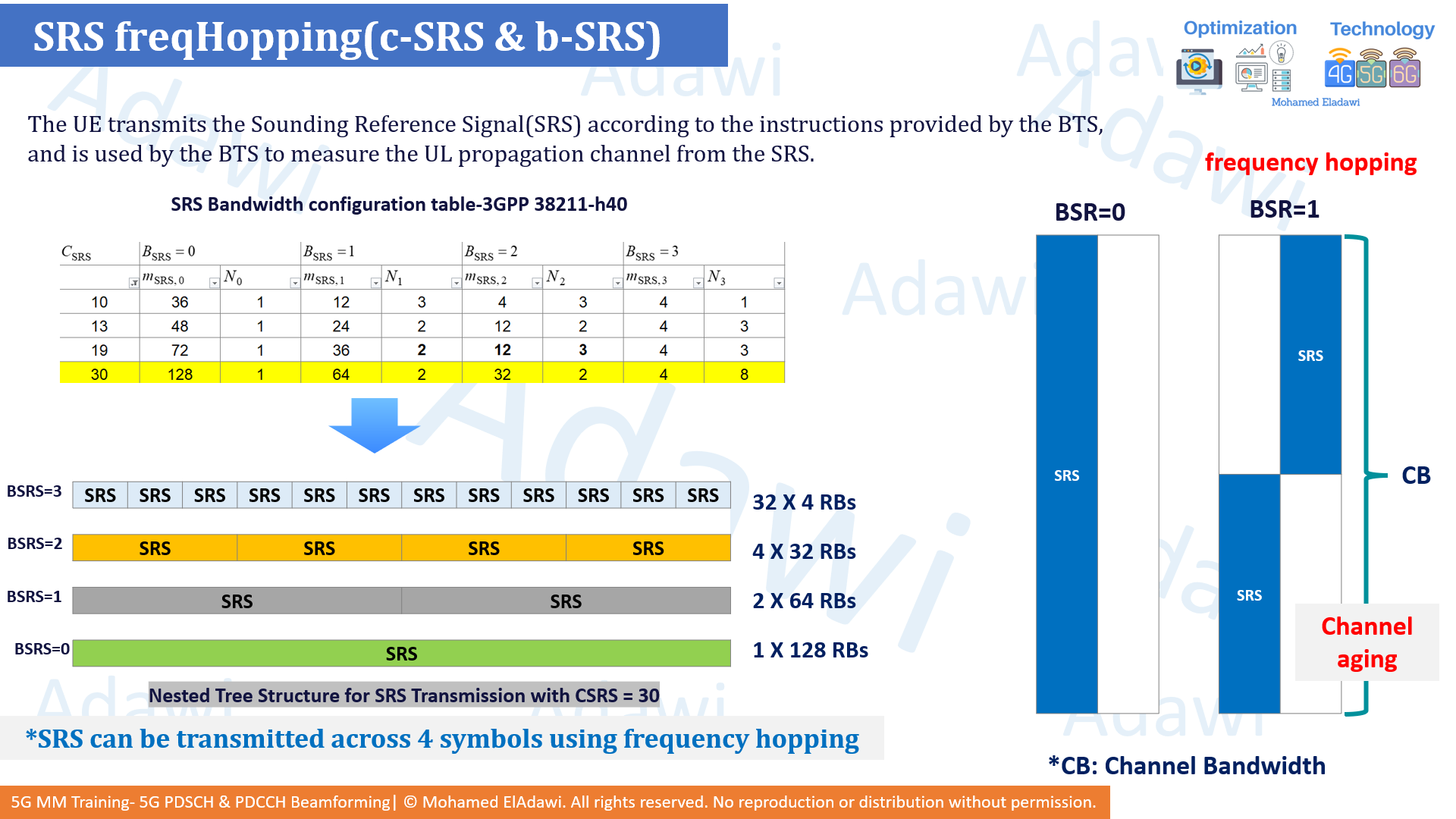
3.3 SRS frequency hopping and SRS gain
One of the main weaknesses of SRS is that it is often transmitted over a wide bandwidth.
This means the UE uplink power is distributed over many resource elements. At cell edge, that can reduce the power density per resource element and make SRS coverage weaker.
A common optimization is SRS frequency hopping. Instead of sending the full SRS bandwidth in one shot, the bandwidth can be split across different symbols. For example, the UE can send SRS over half the bandwidth in one symbol and the other half in the next symbol.
The practical benefit is clear: when the bandwidth is halved, the same UE power is concentrated over fewer resources, so the per-resource power improves. In simple terms, this gives an SRS gain, often explained as roughly 3 dB when the sounding bandwidth is halved.
But this comes with a trade-off. If the channel changes quickly, then the first SRS measurement may become old before the second one is used. This is the channel aging concern.
So frequency hopping improves SRS coverage, but it may reduce estimation freshness when the UE is moving fast.
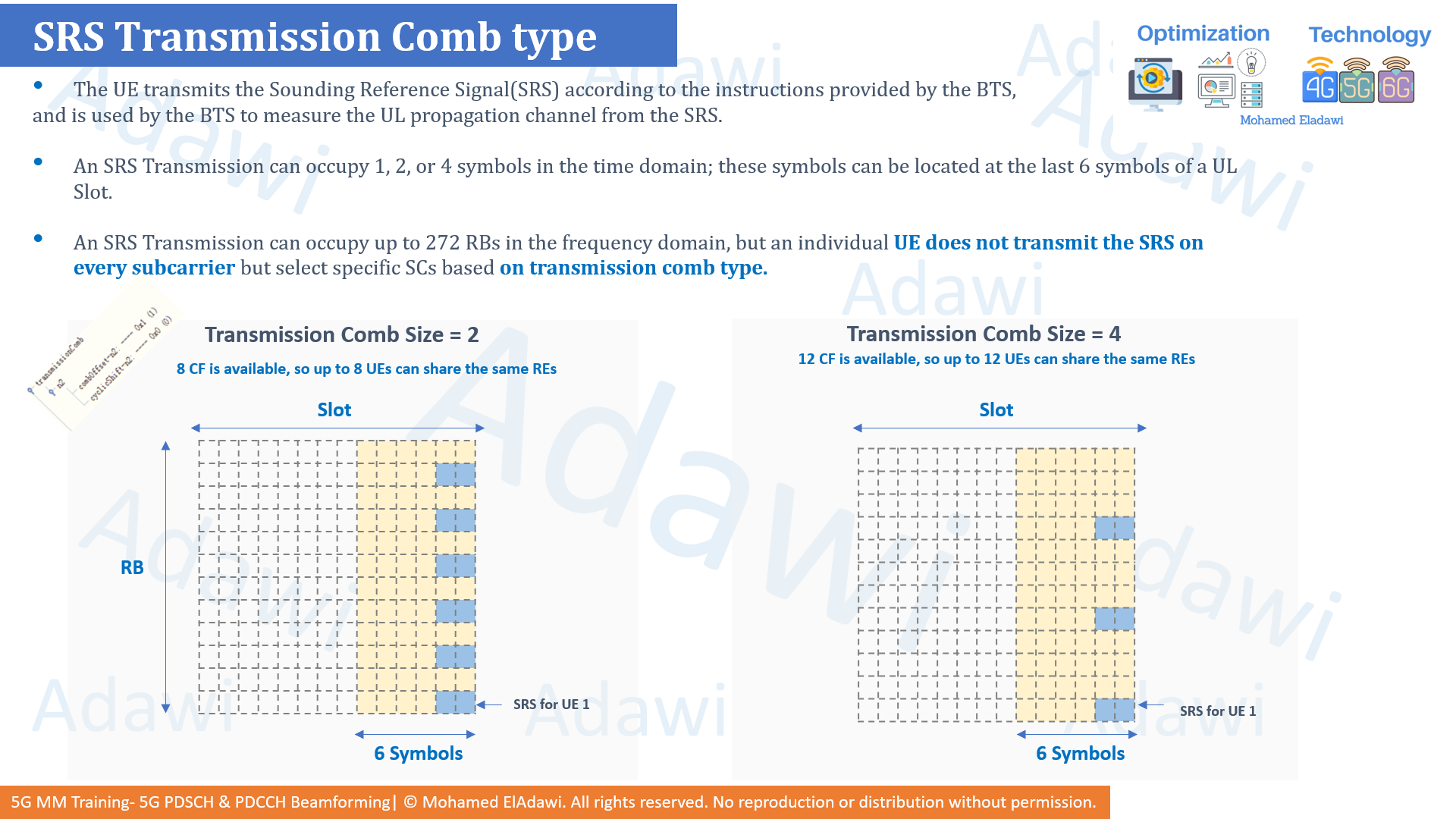
3.4 SRS transmission comb and capacity optimization
Another important optimization topic is SRS capacity when many RRC-connected users need sounding resources.
In NR, the SRS transmission does not have to occupy every subcarrier. It can use a transmission comb pattern.
With transmissionComb = 2, the UE transmits on every second subcarrier. This gives 8 cyclic shifts, so up to 8 UEs can share the same resource elements.
With transmissionComb = 4, the UE transmits on every fourth subcarrier. This increases the available cyclic shifts to 12, so more users can be multiplexed on the same SRS resource.
The gain is higher capacity. The trade-off is that the gNB sees a less dense frequency-domain sounding view, which can reduce how complete the bandwidth observation is.
So comb size is a classic optimization trade-off between capacity efficiency and channel-detail richness.
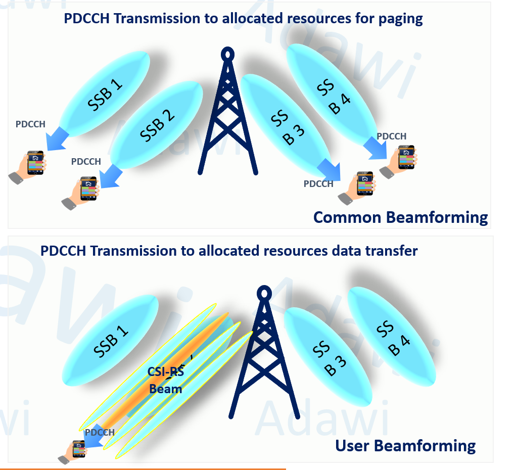
3.5 How PDCCH beamforming works in 5G
Unlike 4G, 5G supports PDCCH beamforming.
From a practical point of view, there are two broad beamforming styles for PDCCH.
The first is common beamforming. This is more suitable for payloads such as paging or system information, where wide-area coverage is more important. In such a case, the PDCCH is more likely to use the same wide beam behavior as the SS/PBCH beams.
The second is user beamforming. When the PDCCH is carrying resource allocation for actual user data, a more directional beam can be used. In this case, the network may align the PDCCH more closely with refined CSI-RS-based directional beams.
Why does this matter? Because a UE may have a good traffic beam on PDSCH, but if the PDCCH is still too weak or not well aligned, the UE may fail to decode the DCI. Then it cannot use the good traffic beam effectively because it never received the control information correctly.
Directional PDCCH beamforming improves control-channel robustness for the target UE, but it also becomes more sensitive to beam switching and beam failure.
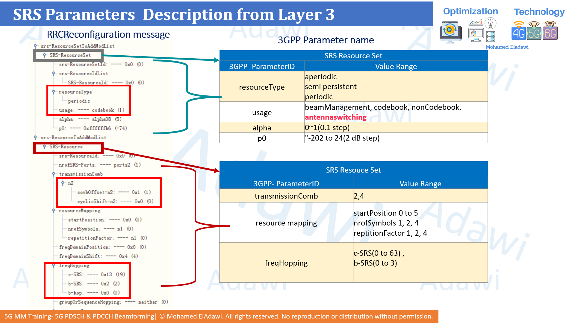
4. Key SRS-related parameters and where to find them
| Parameter | What it controls | Where it appears | Practical note |
|---|---|---|---|
resourceType |
Whether SRS is periodic, semi-persistent, or aperiodic | RRCReconfiguration under SRS Resource Set |
Aperiodic SRS is useful when the gNB wants an extra sounding update on demand |
usage |
Defines the purpose of the SRS resource set | RRCReconfiguration under SRS Resource Set |
If usage is antennaswitching, it is a strong indication that channel reciprocity-based DL sounding is being used |
alpha |
Uplink power-control related scaling | RRCReconfiguration |
Useful for UL power behavior, but not the main beamforming indicator by itself |
p0 |
Uplink SRS power-control offset | RRCReconfiguration |
Important when tuning SRS coverage and interference balance |
SRS-ResourceSetId |
Groups the SRS resources used for a given function | RRCReconfiguration |
Lets the gNB organize multiple SRS configurations for different purposes |
SRS-ResourceId |
Defines the actual sounding resource instance | RRCReconfiguration |
In antenna-switching scenarios, different resources can represent different switching occasions |
transmissionComb |
Subcarrier spacing pattern for SRS mapping | RRCReconfiguration under SRS Resource |
Comb 4 improves multiplexing capacity, but reduces sounding density |
startPosition |
Symbol start position for SRS | RRCReconfiguration under resource mapping |
Helps determine where the SRS sits in time domain |
nrofSymbols |
Number of symbols used by the SRS | RRCReconfiguration under resource mapping |
SRS can occupy 1, 2, or 4 symbols depending on configuration |
repetitionFactor |
Repetition behavior of the SRS resource | RRCReconfiguration under resource mapping |
Can help robustness depending on vendor implementation and use case |
c-SRS |
Basic SRS bandwidth configuration component | RRCReconfiguration under freqHopping |
Read together with b-SRS to understand SRS bandwidth structure |
b-SRS |
Controls SRS bandwidth split / hopping behavior | RRCReconfiguration under freqHopping |
Higher split can improve SRS power density but may increase channel-aging risk |
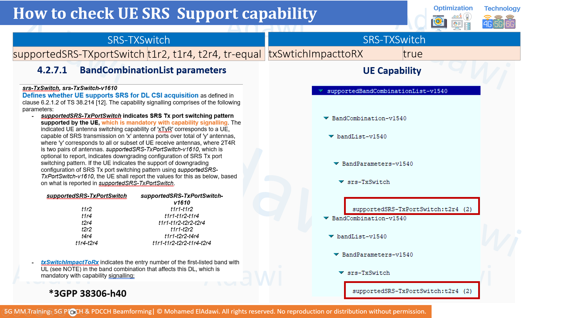
supportedSRS-TXportSwitch |
Declares UE support for TX-port switching patterns such as t1r2, t1r4, t2r4, tr-equal |
UE Capability message under band combination capability | Key field to confirm whether the UE can support antenna switching |
txSwitchImpacttoRX |
Indicates whether TX switching impacts RX behavior | UE Capability message | Useful when assessing device limitations or implementation behavior |
5. Practical example: 2T4R UE with antenna switching
Assume the UE supports 2 transmit paths and 4 receive paths.
If the UE transmits only two SRS signals without switching, the gNB will only learn part of the full receive-side channel condition. That is not enough for accurate downlink beamforming.
So the gNB configures SRS resources with usage = antennaswitching. The UE first sends SRS while one TX path is associated with the first receive-antenna pair. In a later symbol or later triggered occasion, it switches and sends another SRS for the second receive-antenna pair.
Now the gNB can combine the sounding from all receive branches, estimate the downlink propagation more correctly, and derive a better precoding matrix for PDSCH.
This is also why both UE capability support and correct SRS resource design are essential. If either one is missing, SRS-based beamforming may not work as intended.
6. How to verify in real logs and traces
There are two main places to check.
Layer 3 messages
In RRC Reconfiguration, look for:
SRS-ResourceSetToAddModListresourceTypeusageSRS-ResourceIdtransmissionCombfreqHoppingc-SRSb-SRS
A very practical shortcut is this:
- If you see
usage = antennaswitching, the gNB is very likely preparing SRS-based downlink channel sounding for reciprocity-based beamforming. - If this is absent and the configuration instead relies on CSI feedback / PMI behavior, then the network may be using codebook-based beamforming instead.
UE capability message
In the UE capability, check:
supportedSRS-TXportSwitch- Supported patterns such as
t1r2,t1r4,t2r4, ortr-equal txSwitchImpacttoRX
Quick sanity checklist
- Is the deployment TDD?
- Does the UE support the required SRS TX-port switching mode?
- Is
usage = antennaswitchingconfigured? - Are the SRS bandwidth and power settings reasonable for cell-edge users?
- Is the network falling back to codebook-based operation for weak or interference-limited cases?
Summary (Key takeaways)
- SRS-based PDSCH beamforming uses TDD channel reciprocity to estimate the downlink channel and calculate the precoding matrix.
- Antenna switching becomes essential when the UE has fewer TX paths than RX paths, such as 2T4R.
- Frequency hopping can improve SRS power density and coverage, but it introduces a channel-aging trade-off.
- Transmission comb helps increase SRS capacity, but the denser the multiplexing, the less complete the frequency-domain sounding view becomes.
- PDCCH beamforming is a real 5G advantage: common wide beams suit paging/system information, while more directional beams can better support user-specific control delivery.
References
- 3GPP TS 38.211
- 3GPP TS 38.214
- 3GPP TS 38.306
- 3GPP TS 38.331
- 5G NR in Bullets
- 5G NR The next generation wireless access technology third edition
Video for the same
Related articles
- 5G HARQ Explained: Soft Combining, HARQ Processes, ACK/NACK Timing, Codebook Types, Spatial Bundling, and 4G vs 5G Differences
- 5G SSB Explained: Cell Search, Frequency Positioning, Beam Sweeping, and Overhead
- 5G Massive MIMO Fundamentals: Passive vs Active Antenna, MIMO Gains, and Antenna Specifications and Structure
- Deep Dive into 5G CSI-RS
- 5G UL Channels: Deep Dive into Reference Signal Optimization